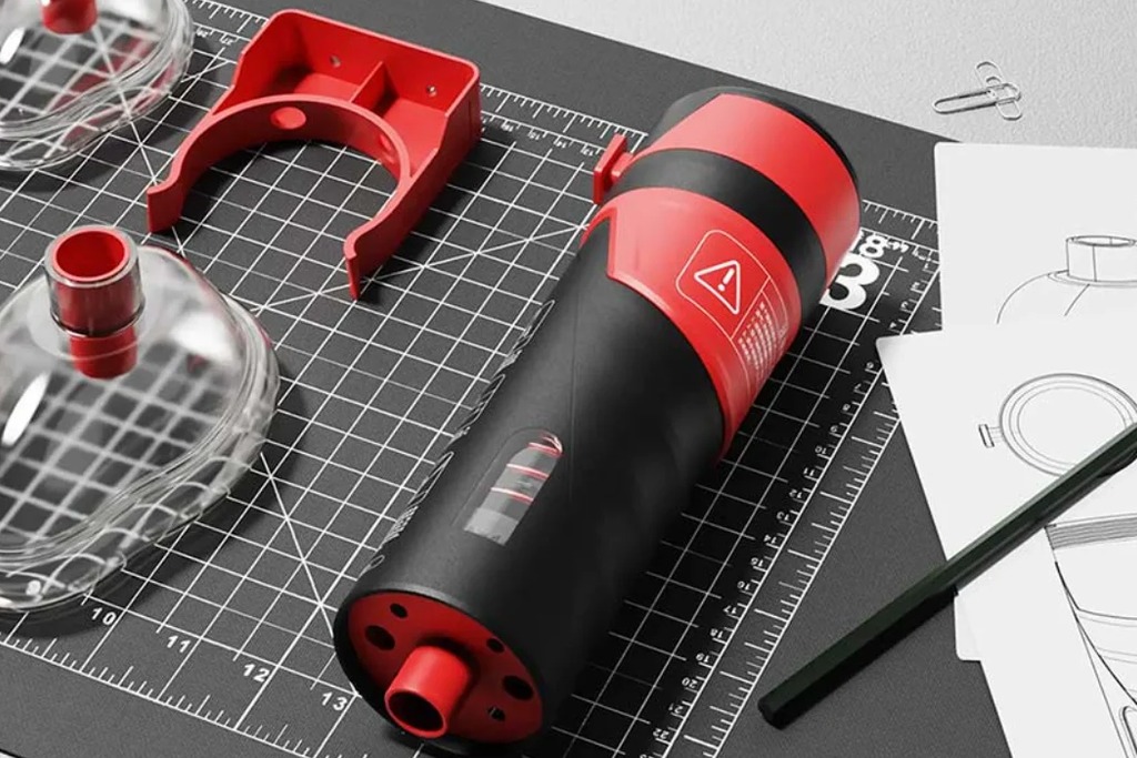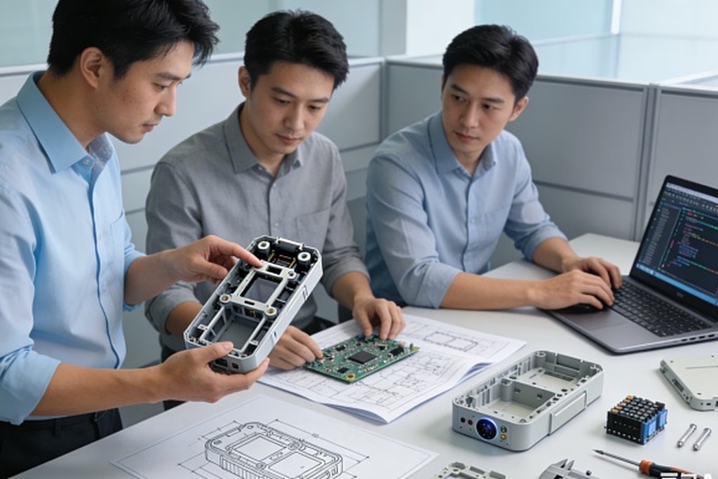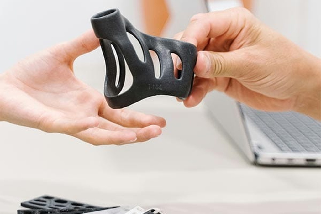

A prototype that costs less is not automatically a bad prototype. A cardboard model, foam mockup, or basic 3D print may be exactly the right tool for answering an early design question.
The problem begins when a low-cost prototype is treated as proof of production readiness.
A polished model may confirm the product’s overall size and appearance while revealing almost nothing about injection-molding behavior, production materials, tolerance stack-up, assembly time, sealing, durability, or cosmetic consistency. If a team approves tooling on the basis of that model, unresolved risks move from inexpensive plastic or foam into machined steel.
At that point, a design issue is no longer just a CAD revision. It may require mold modification, new inserts, additional sliders, repeated tool trials, component rework, delayed certification, or even replacement tooling.
This is why cheap prototypes often lead to expensive tooling problems: not because affordable prototypes are inherently unreliable, but because the wrong prototype creates false confidence.
What You Need to Know in 30 Seconds
- A prototype should be judged by what it proves, not by how realistic it looks.
- Early concept models can be inexpensive because their purpose is limited.
- Before tooling, prototypes must progressively validate form, function, material behavior, tolerances, assembly, and manufacturability.
- 3D printing can produce geometries that injection molding cannot reproduce economically.
- Hand finishing and manual assembly can conceal gaps, warpage, interference, and labor problems.
- A formal DFM review should happen before the production design is frozen and mold steel is cut.
- The most cost-effective prototype is not always the cheapest unit. It is the one that removes the most important uncertainty before the next investment.
Cheap Prototype vs. Cost-Effective Prototype
The words “cheap” and “cost-effective” are often used as if they mean the same thing. In product development, they describe very different outcomes.
A cheap prototype minimizes the immediate quotation. A cost-effective prototype maximizes useful learning for the amount invested.
| Cheap Prototype | Cost-Effective Prototype |
|---|---|
| Selected mainly by unit price | Selected according to the question being tested |
| May use the easiest available material | Uses material properties appropriate to the test |
| Often combines several unverified assumptions | Isolates important risks and produces measurable evidence |
| May look complete without being technically representative | Makes its limitations and level of fidelity clear |
| Can encourage premature design approval | Supports a specific development decision |
| Reduces cost now but may transfer risk downstream | Reduces total development risk and avoids unnecessary tooling changes |
For example, an inexpensive SLA appearance model may be cost-effective for reviewing proportions, branding, button locations, and surface transitions. The same model would be a poor basis for approving a living hinge, snap-fit life, drop resistance, chemical resistance, or injection-molded part tolerance.
The correct question is therefore not:
“How cheaply can we make a prototype?”
It is:
“What must this prototype prove before we spend money on the next stage?”
Why Tooling Changes Are So Much More Expensive
Rapid prototypes are designed to be changed. Production molds are designed to reproduce the same geometry thousands of times.
Before tooling, an engineer can modify a CAD file, print or machine another part, test it, and repeat the process. After tooling begins, the geometry has been translated into mold cores, cavities, parting surfaces, gates, runners, cooling channels, slides, lifters, and ejector systems. A product change can affect several of these elements at once.
The consequences may include:
- Additional CNC or EDM machining
- Welding and re-machining mold steel
- New mold inserts or replacement cores
- Changes to gates, runners, cooling, or ejection
- Re-polishing or re-texturing cosmetic surfaces
- New T0, T1, or T2 trial rounds
- Re-inspection of critical dimensions
- Reassembly and system-level testing
- Updates to drawings, BOMs, work instructions, and quality standards
- Delayed pilot production and market launch
Mold changes are also direction-dependent.
Toolmakers often prefer “steel-safe” conditions. In simplified terms, it is usually easier to remove additional steel from a mold than to put steel back. If a molded feature must become larger, the toolmaker may be able to machine the corresponding mold area further. If the molded feature must become smaller, the tool may require welding, a new insert, or replacement of a core or cavity section.
This is why critical dimensions, shutoffs, snap-fits, sealing surfaces, and cosmetic boundaries should be reviewed with the toolmaker before the design is frozen. A small decision in CAD can determine whether a later adjustment is controlled or disruptive.
The Prototype-to-Tooling Mismatch
Many tooling failures begin because a prototype process and the intended production process obey different rules.
| What the Prototype Appears to Prove | What It May Actually Hide |
| The enclosure can be made | The geometry may require undercuts, slides, lifters, or multiple parts |
| Two halves fit together | Hand sanding, flexible print material, or loose tolerances may be compensating for interference |
| The wall is strong enough | The printed layer structure and prototype material may not represent molded resin behavior |
| The surface looks premium | Primer, paint, filler, and manual polishing may hide sink marks, weld lines, gates, and ejector marks |
| The snap-fit works | It may not survive repeated cycles in the production material |
| The product can be assembled | Skilled prototype technicians may be using slow, non-repeatable manual adjustments |
| The seal works | A single carefully assembled sample does not prove tolerance variation or production consistency |
| The dimensions are correct | The prototype may not represent molding shrinkage, warpage, or process capability |
The issue is not that rapid prototyping is inaccurate or unhelpful. It is that every process has a validation boundary. Problems occur when teams claim more evidence than the chosen method can provide.
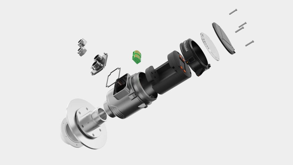
1. The Prototype Answers the Wrong Question
Every prototype should begin with a test objective.
An appearance model might answer:
- Are the proportions appropriate?
- Does the product communicate the intended brand?
- Are buttons and indicators visually clear?
An ergonomic model might answer:
- Is the grip comfortable?
- Can users reach the controls?
- Is the weight distribution acceptable?
A functional engineering prototype might answer:
- Does the mechanism work under load?
- Can the electronics manage heat?
- Does the battery meet the operating target?
A production-intent prototype might answer:
- Do production materials meet the functional requirements?
- Are molded tolerances compatible with assembly and sealing?
- Can the design be manufactured, inspected, and assembled repeatedly?
When a team orders one low-cost prototype and expects it to answer all four groups of questions, it usually answers none of them completely.
A better approach is to define the decision that each prototype must support, the variables it represents accurately, the variables it deliberately simplifies, and the criteria for passing the test.
2. 3D Printing Hides Injection-Molding Constraints
Additive manufacturing gives designers valuable geometric freedom. It can produce internal channels, vertical walls, complex cavities, and nested features without the same parting, ejection, and tooling constraints as injection molding.
That freedom is excellent for experimentation. It can be dangerous when the same CAD geometry is sent directly for tooling.
Common differences include:
Missing Draft Angles
Injection-molded parts normally need taper on surfaces parallel to the direction of mold opening so the part can be ejected without sticking, scraping, or excessive force. The required draft depends on material, depth, texture, wall thickness, and mold design; it is not one universal number. Protolabs’ draft guidance recommends considering all of these variables rather than applying a single rule blindly.
A printed part does not need to leave a mold cavity, so zero-draft walls may appear completely acceptable in the prototype.
Hidden Undercuts
A 3D printer can build a hook, side opening, or recessed feature directly. An injection mold may need a slider, lifter, collapsible core, hand-loaded insert, or product redesign to release the same geometry.
These mold actions add cost, size, maintenance, cycle time, and failure points. An inexpensive print can therefore validate a feature that is disproportionately expensive to mold.
Inconsistent Wall Thickness
Thick solid areas may print successfully, but molded plastic cools and shrinks. Uneven sections can create sink marks, voids, internal stress, and warpage. Uniform walls, appropriate ribs, and cored geometry are normally preferred. Injection-molding wall-thickness guidance emphasizes consistent sections and appropriately proportioned adjacent features.
Impossible Parting and Ejection Conditions
A prototype may look clean because it has no parting line, gate, or ejector marks. A real mold must open, fill, cool, and release the part. Those requirements influence both engineering and visual design.
If the industrial design reserves no acceptable location for these features, the first DFM review may force visible changes after stakeholders have already approved the appearance.
3. The Prototype Uses the Wrong Material
“ABS-like,” “rubber-like,” and “nylon-like” do not mean identical to a specified production resin.
Prototype materials can differ from production materials in:
- Elastic modulus and flexibility
- Impact strength
- Fatigue behavior
- Creep under sustained load
- Friction and wear
- Heat resistance
- Chemical resistance
- Moisture absorption
- UV stability
- Flame performance
- Shrinkage
- Color, gloss, and texture response
These differences matter for clips, living hinges, press-fits, gears, seals, latches, thin walls, and structural supports.
Imagine a snap-fit that works in a flexible printed nylon. If the production part changes to a stiffer resin to improve heat resistance or cosmetic quality, the same geometry may require more assembly force or crack after repeated use. Conversely, a rigid SLA part may fail during early testing even though a properly designed molded polypropylene feature would work.
Material selection must connect functional requirements with manufacturing behavior. OPD’s material selection guide explains why prototype method, product requirements, and final production process should be evaluated together.
When material behavior is critical, teams may need CNC prototypes in an engineering-grade material, cast parts with known limitations, sample plaques, supplier data, simulation, or low-volume molded parts before committing to production tooling.
4. Hand Finishing Creates False Precision
Prototype workshops can make an impressive model fit beautifully. Technicians may sand a surface, enlarge a hole, adjust a clip, add adhesive, shim a gap, polish an edge, or selectively assemble the best combination of parts.
That craftsmanship is valuable for presentation models. It is not evidence of a capable production process.
Mass production introduces variation across:
- Mold cavities
- Resin batches
- Machine settings
- Cooling conditions
- Components from different suppliers
- Operator technique
- Adhesive or gasket application
- Part storage and moisture exposure
If an assembly works only because one prototype was manually tuned, the design may fail when parts are selected randomly from normal production variation.
The solution is not simply to demand a more accurate prototype. The team must define critical dimensions, realistic tolerances, datum structures, inspection methods, and tolerance stack-up across the full assembly.
5. Manual Assembly Hides Production Labor
A prototype technician may spend an hour routing cables, aligning a gasket, holding internal components, tightening screws in a particular sequence, and correcting minor interference. At a prototype quantity of one, this may be acceptable.
At production volume, the same sequence can create:
- Excessive assembly time
- Operator fatigue
- Trapped or damaged wires
- Missing fasteners
- Uneven compression
- Cosmetic scratches
- Rework and inconsistent quality
- Complex fixtures and training requirements
A production-ready design must consider Design for Assembly as well as Design for Manufacturing.
Useful questions include:
- Can components be installed in only one correct orientation?
- Are fasteners accessible with standard tools?
- Can wires be routed without being pinched?
- Do parts self-locate before fastening?
- Can adhesives, seals, and thermal materials be applied consistently?
- Are torque, insertion force, and compression requirements measurable?
- Can the finished product be tested without partial disassembly?
If the prototype build does not record assembly time, difficulties, adjustments, and rework, the team loses valuable production information.
6. Cosmetic Finishing Hides Molded-Part Defects
Paint and manual finishing can create a surface that looks more uniform than an as-molded production part.
They can conceal:
- Sink marks over ribs and bosses
- Weld or knit lines
- Flow marks
- Gate blush
- Ejector witness marks
- Warpage
- Uneven texture
- Color variation
- Read-through from internal structures
This becomes especially risky when the commercial product is expected to use molded-in color and texture rather than secondary painting.
Cosmetic requirements should be translated into CMF specifications, texture references, gloss ranges where appropriate, parting-line expectations, gate and ejector restrictions, and approved limit samples. A visually perfect presentation prototype should not be used as the only cosmetic standard for an injection-molded part unless its construction and finishing differences are clearly documented.
7. A Single Prototype Does Not Reveal Variation
One good unit proves that one unit can work.
It does not prove that all parts within realistic manufacturing tolerances will work.
This is particularly important for:
- Waterproof or dust-resistant enclosures
- Optical alignment
- Gear and motor systems
- Battery doors and latches
- Snap-fits
- Wearable contact surfaces
- Press-fitted bearings or inserts
- Buttons and light pipes
- Multi-part cosmetic gaps
A seal may pass when the enclosure is at one end of its tolerance and the gasket at the other favorable end. A production batch may contain the opposite combination.
Engineering teams should identify critical-to-quality characteristics and test worst-case or representative tolerance conditions. Depending on the product, this may involve multiple engineering prototypes, tolerance analysis, environmental testing, reliability cycles, cavity measurements, and pilot-run data.
8. The Prototype Is Built from the Wrong CAD Version
Prototype projects often move quickly. A mechanical engineer updates a boss, an electronics engineer changes the PCB outline, and an industrial designer adjusts an external surface. If files are exchanged informally, the “approved prototype” may contain a mixture of versions.
That becomes dangerous when the toolmaker receives a different model from the one that was tested.
Before tooling release, teams should control:
- 3D CAD revision
- 2D drawings and tolerances
- PCB dimensions and connector locations
- BOM revision
- CMF specifications
- Firmware and test configuration
- Approved deviations
- Prototype test results
- Open issues and risk ownership
Design freeze does not mean the product can never change. It means the released version is clearly identified, validated for its development stage, and changed only through a documented approval process.
9. DFM Is Performed After the Design Is “Finished”
Design for Manufacturing is most valuable when it can still influence the design.
NIST describes DFM as a way to identify and eliminate manufacturing problems during design, reducing redesign, product cost, and lead time. That logic is straightforward: a manufacturability issue found while geometry is still flexible is an engineering decision; the same issue found after tooling is a recovery project. See NIST’s overview of integrating DFM with CAD.
A meaningful injection-molding DFM review should consider:
- Material and process compatibility
- Nominal and transition wall thickness
- Draft direction and angle
- Undercuts and mold actions
- Ribs, bosses, gussets, and snap-fits
- Parting-line location
- Gate type and location
- Ejection strategy
- Shrinkage and warpage risk
- Weld lines and air traps
- Cooling and cycle-time considerations
- Cosmetic surfaces and texture
- Critical dimensions and steel-safe strategy
- Mold construction, expected volume, and service life
OPD’s injection-molding design guidelines provide a more detailed review of the part-design rules that should be considered before tooling.
What Each Prototype Stage Should Validate
No single prototype needs maximum fidelity in every category. Fidelity should increase according to risk and development stage.
| Prototype Stage | Main Purpose | What Can Be Simplified | What Should Not Be Claimed |
| Concept mockup | Explore size, layout, and basic interaction | Material, finish, internal architecture | Production performance or manufacturability |
| Appearance model | Review form, CMF direction, branding, visual hierarchy | Electronics and some internal structures | Mechanical reliability or molded cosmetic consistency |
| Ergonomic prototype | Test grip, reach, fit, comfort, and human interaction | Final materials and electronics when not relevant | Final durability or assembly performance |
| Functional prototype | Prove a mechanism, electronic function, or technical principle | Final appearance and some packaging | Complete product validation |
| Engineering prototype | Integrate mechanical, electronic, firmware, and thermal systems | Some production tooling and finishes | Stable production capability |
| Production-intent prototype | Validate materials, interfaces, tolerances, assembly, and test requirements | Only documented non-critical elements | Mass-production consistency without pilot data |
| Rapid or bridge tooling | Produce low-volume parts in or near production materials and processes | Full hardened-tool life and maximum automation | Long-term high-volume yield without further validation |
Rapid tooling can be useful when material and process fidelity matter but the project is not ready for long-life production tooling. Formlabs’ rapid tooling guide describes how short-run molds and related methods can help validate designs and materials before mass production. The appropriate method depends on part size, geometry, material, quantity, test purpose, and future production plan.
A Hypothetical Example: The Enclosure That “Already Worked”
Consider a hypothetical connected-device enclosure.
The team approves a low-cost SLA prototype because:
- The two enclosure halves fit.
- The PCB can be installed.
- The product looks close to the rendering.
- The buttons can be pressed.
After the mold DFM review and first trial, several problems appear:
- The vertical cosmetic walls have insufficient draft for the selected texture.
- Thick areas around the screw bosses produce visible sink marks.
- A side opening creates an undercut and requires a slider.
- The gate location creates a visible flow line on the front surface.
- The molded halves warp differently, increasing the external gap.
- The gasket groove does not maintain reliable compression across tolerance limits.
- The assembly depends on a technician manually moving a cable away from a screw boss.
None of these problems contradicts the successful SLA prototype. The prototype proved appearance and nominal fit. The team mistakenly treated it as evidence of moldability, material behavior, tolerance capability, and repeatable assembly.
The lesson is not to avoid SLA. It is to define what SLA can prove, then add the engineering analysis and higher-fidelity validation required before tooling.
How to Reduce Prototype Cost Without Increasing Tooling Risk
Controlling development cost is important. The goal is to remove waste without removing evidence.
Prototype the Highest-Risk Questions First
Do not spend heavily reproducing low-risk decorative details while the core mechanism, thermal design, antenna, sealing strategy, or material choice remains uncertain.
Use Mixed-Fidelity Assemblies
Not every part requires the same process. A prototype can combine CNC-machined critical components, 3D-printed housings, off-the-shelf fasteners, and simplified cosmetic parts. Invest precision where it changes the decision.
Test Subsystems Before the Full Product
A seal test coupon, snap-fit strip, optical stack, hinge rig, or thermal test enclosure may answer a question faster and more clearly than a complete showcase model.
Design for the Production Process Early
Draft, wall thickness, parting strategy, assembly access, and tolerance architecture should enter the mechanical design before the final prototype, not after it.
Request DFM Before the Final Design Freeze
Early toolmaker or manufacturing-engineer input can reveal expensive geometry while changes are still easy. A second DFM gate can confirm the released tooling package.
Document Prototype Limitations
Every review should state which materials, processes, dimensions, finishes, and functions are representative—and which are not. This prevents stakeholders from approving the product based on assumptions the prototype was never intended to test.
Use Rapid Tooling When It Retires a Critical Risk
Low-volume molding can be justified when teams must validate production resin, molded surface quality, assembly behavior, sealing, or real process variation. It should be selected because it answers an important question, not merely because it is labeled “rapid.”
Pre-Tooling Validation Checklist
Before releasing a design for production tooling, confirm the following.
Product and Design
- Product requirements are current and measurable.
- Industrial design, mechanical architecture, and CMF are approved.
- The intended manufacturing process is defined for every custom part.
- Critical user, safety, and performance risks have been tested.
Materials
- Production resin grades or acceptable specifications are identified.
- Material properties match mechanical, thermal, chemical, cosmetic, and compliance needs.
- Prototype material differences and their effects are documented.
- Shrinkage and environmental behavior have been considered.
Mechanical Engineering
- Wall thickness and transitions have been reviewed.
- Draft is appropriate for geometry and texture.
- Undercuts and mold actions are understood.
- Ribs, bosses, snap-fits, fasteners, and inserts are validated.
- Parting lines, gates, ejector locations, and cosmetic surfaces are agreed.
- Critical dimensions and tolerance stacks are documented.
- Steel-safe adjustment strategy is defined where appropriate.
Assembly and Testing
- Assembly order and tool access have been evaluated.
- Cables, gaskets, adhesives, and thermal materials can be installed consistently.
- Critical assembly forces and torques are specified.
- End-of-line testing and inspection access are considered.
- Engineering prototypes have been tested against defined pass/fail criteria.
Documentation and Approval
- Released CAD and drawings match the tested design.
- BOM, PCB, firmware, and CMF revisions are aligned.
- A formal DFM review is complete and major risks are closed or accepted.
- Remaining deviations have owners and closure plans.
- Tooling scope, mold life, cavities, materials, texture, ownership, maintenance, and trial deliverables are agreed.
If several of these items are unknown, the project may need another targeted prototype or engineering review before tooling.
How OPD Connects Prototyping with Mold Development
The handoff between prototype and tooling should not be a blind transfer of CAD files.
At OPD Design, product prototyping is used to evaluate appearance, ergonomics, function, engineering integration, and manufacturability according to the project stage. The purpose is not simply to produce a model, but to generate evidence for the next design decision.
Once the design reaches the appropriate level of maturity, OPD’s mold development process connects:
- Design freeze and risk assessment
- DFM analysis and engineering optimization
- Mold design and manufacturing
- T0, T1, and T2 trials
- Dimensional and cosmetic correction
- Pilot production and PVT
- Mass-production ramp-up
This connected approach helps industrial designers, mechanical engineers, electronics teams, prototype suppliers, toolmakers, and manufacturing partners work from the same design intent and controlled data.
For a broader view of the full development sequence, read our prototype-to-mass-production guide.
The Best Prototype Is the One That Prevents the Next Expensive Mistake
Product teams do not need the most expensive prototype at every stage. They need the right evidence before each major commitment.
An early model can be fast and inexpensive. An engineering prototype should expose integration problems. A production-intent build should challenge materials, tolerances, assembly, and performance. DFM should translate the approved design into a realistic mold and production strategy.
When those stages are skipped or blurred together, the apparent savings from a cheap prototype often return as mold modifications, repeated trials, lower yield, manual rework, and launch delays.
The principle is simple:
Do not ask whether the prototype looks finished. Ask whether it has retired the risks that would be expensive to discover after tooling.
If you are preparing a consumer electronic product, IoT device, wearable, healthcare product, beauty device, children’s product, or another custom hardware product for tooling, OPD Design can review your current prototype, identify unresolved engineering and DFM risks, and build a controlled path toward production.
Contact OPD Design to discuss your prototype, target materials, production volume, and tooling requirements.