
Building one convincing prototype is not the same as manufacturing 1,000 or 10,000 consistent products.
A prototype may prove that an idea works. Mass production must prove that the same product can be manufactured repeatedly, at the required quality, cost, and delivery schedule. The transition between these two points is where many hardware projects encounter unexpected redesigns, tooling changes, component shortages, certification delays, and quality problems.
China offers a highly connected ecosystem for industrial design, engineering, prototyping, tooling, electronics, and manufacturing. However, access to this ecosystem does not automatically guarantee a successful launch. Companies still need a structured New Product Introduction process, clear technical documentation, appropriate validation, and reliable quality control.
This guide explains how to move from prototype to mass production in China, including the purpose of POC, EVT, DVT, PVT, tooling trials, pilot production, and production ramp-up.
What You Need to Know in 30 Seconds
Moving from prototype to mass production usually involves five broader phases:
- Define the product and verify technical feasibility.
- Develop and test functional engineering prototypes.
- Validate the complete product design.
- validate tooling and the manufacturing process through pilot production.
- Scale production while maintaining quality and controlling changes.
The most important principle is simple:
Do not move to the next phase merely because a prototype looks good. Move forward only when the current phase has answered its key technical, commercial, and manufacturing questions.
Prototype to Mass Production at a Glance
| Stage | Primary Question | Typical Output |
|---|
| Product Definition | What should we build, for whom, and at what cost? | Product requirements document |
| POC | Can the critical technology work? | Proof-of-concept prototype |
| Design and Engineering | How should the product look, function, and be assembled? | CAD, schematics, PCB design, firmware architecture |
| EVT | Does the engineered product work? | Functional engineering prototypes |
| DVT | Does the complete design meet its requirements? | Production-intent design |
| Tooling | Can the parts be reproduced accurately? | Validated molds, fixtures, and production parts |
| PVT | Can the factory build the product consistently? | Pilot production units |
| Mass Production | Can quality and delivery remain stable at volume? | Saleable production units |
The exact sequence may vary by product. A simple non-electronic consumer product may require fewer validation rounds, while a connected device, medical product, or complex electromechanical system may require additional testing and documentation.
Why Develop and Manufacture a Product in China?
China is no longer only a destination for low-cost manufacturing. Major industrial regions combine product design, engineering, component sourcing, prototype workshops, mold makers, assembly factories, testing laboratories, and logistics providers within one connected ecosystem.
Shenzhen and the surrounding Greater Bay Area are especially valuable for electronic and smart hardware products. Engineers can access PCB suppliers, sensors, batteries, displays, motors, plastics, metal fabrication, and specialist manufacturers without coordinating an entirely separate supply chain for every component.
This proximity can provide several practical advantages:
- Faster prototype iterations
- Greater access to components and manufacturing processes
- More supplier options
- Easier communication between designers, engineers, and factories
- Faster tooling adjustments and production troubleshooting
- Support for both low-volume pilot runs and larger production orders
These advantages are most valuable when the project is managed as a connected development process. If industrial design, mechanical engineering, electronics, prototyping, and manufacturing are handled in isolation, the product may still suffer from incompatible files, late engineering changes, and unclear responsibilities.
Step 1: Define the Product Before Building It
A successful manufacturing project begins with a clear product definition.
Many teams start by requesting a prototype quote before agreeing on the intended user, core functions, target market, expected volume, or target production cost. This usually results in an impressive model that is difficult to convert into a commercially viable product.
The initial product brief should define:
- Target users and use scenarios
- Core and optional functions
- Product dimensions and weight expectations
- Performance requirements
- Intended materials and finish
- Power, battery, connectivity, and charging requirements
- Mobile app or cloud requirements
- Target retail and manufacturing cost
- Estimated first-order and annual volume
- Intended sales markets
- Relevant safety and compliance requirements
- Packaging and shipping constraints
- Target launch date
It is also useful to separate requirements into three categories:
- Must-have requirements
- Preferred requirements
- Future-version requirements
This prevents the first generation from becoming overloaded with features that increase development cost, technical risk, and time to market.
Key Deliverables
Before proceeding, the team should have:
- A product requirements document
- A preliminary feature list
- Target cost and volume assumptions
- Target market and compliance plan
- Initial development schedule
- Clear approval responsibilities
Step 2: Build a Proof of Concept
A proof of concept, or POC, answers the question: can the most uncertain part of the idea work?
The POC does not need to look like a finished product. It may use development boards, off-the-shelf components, temporary wiring, 3D-printed parts, or a simplified software interface. Its purpose is to test technical feasibility before significant resources are invested in industrial design and tooling.
For example:
- A wearable device POC may test sensor accuracy and signal quality.
- A beauty device POC may test heat, vibration, light, or fluid-delivery performance.
- An IoT product POC may test wireless connectivity and cloud communication.
- A portable medical product POC may test the core measurement principle.
- A service robot POC may test navigation, motors, and obstacle detection.
The POC stage should focus on the highest-risk assumptions. If battery life, antenna performance, thermal control, or sensing accuracy could make the product commercially unviable, test those issues early.
POC Exit Criteria
The project can move forward when:
- Core technical feasibility has been demonstrated.
- Major technical risks are understood.
- Performance is sufficient to justify further development.
- The approximate product architecture is realistic.
- The team has a clear plan for unresolved issues.
A successful POC does not mean the product is ready to manufacture. It means the project has enough evidence to begin integrated product development.
Step 3: Develop the Industrial Design and Engineering Architecture
Once feasibility is established, industrial designers and engineers convert the idea into a complete product.
Industrial design defines the appearance, user interaction, ergonomics, brand language, materials, colors, and finishes. Engineering determines how the product functions, fits together, manages heat, protects electronic components, and survives real-world use.
These disciplines should develop together.
If industrial design is completed without mechanical or electronic input, the approved shape may not leave enough room for the battery, PCB, antenna, connectors, fasteners, airflow, or structural supports. Redesigning the enclosure later can affect both the appearance and project schedule.
An integrated development process may include:
- Industrial design concepts
- Ergonomic and usability studies
- Mechanical architecture
- Internal component layout
- PCB schematic and layout
- Sensor and component selection
- Battery and power management
- Antenna design
- Thermal management
- Firmware development
- Application and cloud architecture
- Material and CMF development
- Preliminary assembly planning
The team should also begin Design for Manufacturing and Design for Assembly analysis during this stage—not after the product has already been approved.
Key Deliverables
Depending on the product, deliverables may include:
- Approved industrial design
- 3D CAD models
- Two-dimensional engineering drawings
- Electronic schematics
- PCB layout and Gerber files
- Preliminary bill of materials
- Firmware and software architecture
- CMF specifications
- Preliminary test plan
Step 4: Build the Right Types of Prototypes
“Prototype” is a broad term. One prototype rarely answers every development question.
Different prototypes should be created for different purposes.
Appearance Prototype
An appearance prototype evaluates size, proportions, color, surface finish, branding, and visual quality. It may look realistic but contain little or no working electronics.
Ergonomic Prototype
An ergonomic prototype evaluates grip, comfort, reach, button placement, wearing experience, balance, and user interaction.
Functional Prototype
A functional prototype tests the product’s primary functions. Its enclosure may be simplified, but its electronics, sensors, mechanisms, or software should generate meaningful performance data.
Engineering Prototype
An engineering prototype combines the mechanical, electronic, and software systems. It helps identify tolerance, assembly, thermal, antenna, power, and system-integration problems.
Pre-Production Prototype
A pre-production prototype uses production-intent materials, components, manufacturing methods, and finishes wherever possible. It should represent the design that will be validated before mass production.
Common product prototyping methods include:
- SLA or SLS 3D printing
- CNC machining
- Sheet-metal fabrication
- Laser cutting
- Silicone molding and vacuum casting
- Prototype PCB assembly
- Soft tooling
- Low-volume injection molding
The method should be selected according to the question being tested. A 3D-printed enclosure may be suitable for ergonomic evaluation but cannot fully predict injection-molding defects, production tolerances, or final surface quality.
Step 5: Conduct DFM and Supply Chain Review
Before committing to tooling, the product should undergo a formal Design for Manufacturing review.
DFM evaluates whether each part can be manufactured reliably and economically using the selected process. Design for Assembly evaluates whether those parts can be assembled efficiently and consistently.
For injection-molded plastic parts, the review may examine:
- Wall thickness
- Draft angles
- Ribs and bosses
- Undercuts
- Parting lines
- Gate and ejector-pin locations
- Sink marks and warping risks
- Surface texture
- Material shrinkage
- Tolerance stack-up
For electronic assemblies, the review may examine:
- Component availability and lifecycle
- PCB panelization
- SMT assembly requirements
- Test-point access
- Connector placement
- Antenna clearance
- Heat dissipation
- Firmware flashing
- Calibration
- End-of-line testing
The supply chain team should also review the bill of materials. A design may work technically but remain unsuitable for mass production if it relies on components with high minimum order quantities, long lead times, unstable pricing, or no approved alternatives.
Questions to Resolve Before Tooling
- Is the design compatible with the intended manufacturing processes?
- Are the critical components available at the required volume?
- Are alternative components approved?
- Can the product be assembled without excessive manual work?
- Can critical functions be tested efficiently on the production line?
- Are cosmetic quality standards clearly defined?
- Does the estimated unit cost still support the business model?
Step 6: Complete EVT
EVT usually stands for Engineering Validation Test or Engineering Verification Test. Its purpose is to prove that the engineered product functions as intended.
EVT units often use rapid-prototype enclosures, early tooling, or low-volume production processes. They should integrate the key mechanical, electronic, firmware, and software systems closely enough to expose system-level issues.
Typical EVT testing may include:
- Core functional performance
- Power consumption and battery life
- Charging behavior
- Thermal performance
- Sensor accuracy
- Wireless connectivity
- Antenna performance
- Motor or mechanism operation
- Firmware stability
- Mechanical fit and assembly
- Basic drop, vibration, or environmental testing
- Early usability evaluation
Failures during EVT are expected. The purpose of the stage is to discover and correct them before tooling and certification make changes more expensive.
Each problem should be documented, assigned, corrected, and retested. Design changes must also be reflected across CAD, drawings, PCB files, firmware, and the bill of materials.
EVT Exit Criteria
EVT is generally complete when:
- Core functions meet the product requirements.
- Major engineering risks have been resolved.
- Mechanical, electronic, and software systems work together.
- Remaining issues have defined corrective actions.
- The design is stable enough to build production-intent units.
Step 7: Complete DVT and Prepare for Compliance
DVT, or Design Validation Test, evaluates whether the complete product design meets its functional, reliability, usability, cosmetic, and regulatory requirements.
Unlike early prototypes, DVT units should closely represent the intended production product. Production materials, critical components, finishes, and assembly methods should be used wherever practical.
DVT testing may include:
- Full functional verification
- Battery and charging tests
- Drop and impact testing
- Temperature and humidity testing
- Vibration testing
- Ingress-protection testing
- Button and connector life-cycle tests
- Material and surface durability
- Chemical or cleaning resistance
- Electromagnetic compatibility pre-testing
- Electrical safety evaluation
- Packaging and transportation testing
- User and usability testing
The exact test plan depends on the product category and target market.
A wireless consumer device sold in the United States and European Union may require different regulatory work from a medical device, children’s product, or industrial machine. Requirements involving CE conformity, FCC equipment authorization, RoHS, REACH, UL standards, FDA regulations, IEC standards, or battery transportation should be identified early with qualified compliance specialists.
Certification planning should not begin after the design has been frozen. Antenna layout, power supply design, materials, batteries, labels, user instructions, and even enclosure openings can affect compliance.
OPD provides compliance and certification support as part of the development process, helping teams consider target-market requirements before production.
DVT Exit Criteria
The design may be frozen when:
- Product requirements have been verified.
- Reliability targets have been met.
- Critical compliance risks have been addressed.
- Manufacturing materials and components are approved.
- Cosmetic standards are defined.
- Major design changes are no longer expected.
- Production documentation is controlled and complete.
Step 8: Develop and Validate Production Tooling
After the design has reached sufficient maturity, production tooling can begin.
For plastic products, this may include injection molds. Other products may require die-casting tools, stamping dies, extrusion dies, cutting fixtures, welding fixtures, assembly jigs, calibration equipment, or automated test fixtures.
Injection-mold development commonly includes several trial stages:
- T0: The first mold trial used to check whether the mold operates and produces a complete part.
- T1: A refined trial used to evaluate dimensions, fit, molding defects, and early surface quality.
- T2 and later trials: Additional rounds used to correct remaining dimensional, cosmetic, or process problems.
The number of trials depends on part complexity, material behavior, cosmetic expectations, and the quality of the initial design.
Trial parts should be inspected against approved drawings. The team should assess:
- Critical dimensions
- Part fit and tolerance
- Warpage and shrinkage
- Sink marks, weld lines, and flow marks
- Gate and ejector marks
- Texture and gloss
- Color consistency
- Assembly performance
- Structural strength
Do not approve a mold merely because it can produce a recognizable part. It must produce parts consistently within the required quality and dimensional limits.
OPD’s mold development process connects DFM, mold design, T0/T1/T2 trials, tooling refinement, pilot production, and mass-production introduction.
Step 9: Establish the Production System
A complete product design is only one part of production readiness. The factory must also establish a repeatable process for building and testing it.
Production preparation may include:
- Approved supplier list
- Final bill of materials
- Incoming inspection requirements
- Assembly work instructions
- Standard operating procedures
- Production line layout
- Operator training
- Firmware flashing procedures
- Calibration processes
- Test fixtures
- End-of-line functional tests
- Cosmetic inspection standards
- Traceability requirements
- Rework procedures
- Packaging instructions
- Quality control plan
The team should define what constitutes an acceptable product. Terms such as “premium finish,” “strong connection,” or “good assembly” are too subjective for production control.
Requirements should be measurable whenever possible. Cosmetic standards can be supported with limit samples showing acceptable and unacceptable scratches, gaps, color differences, or molding marks.
A signed golden sample should be retained as the physical reference for future production.
Step 10: Run PVT or Pilot Production
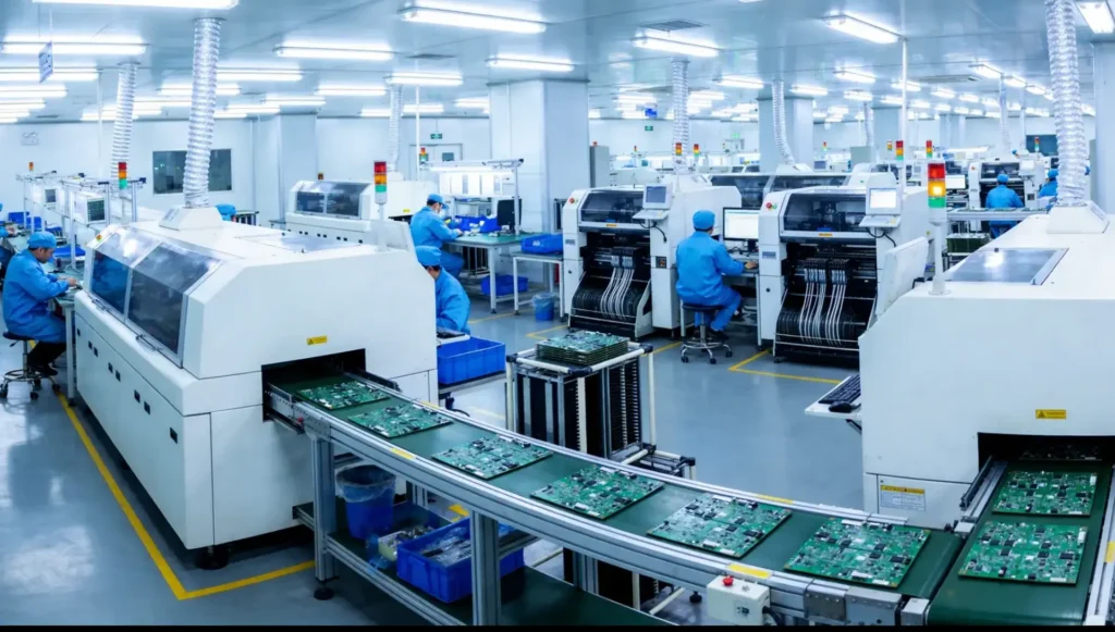
PVT, or Production Validation Test, determines whether the factory can manufacture the approved design consistently using the intended production line, tooling, operators, suppliers, work instructions, and test procedures.
This is a validation of the manufacturing process—not another ordinary prototype build.
The pilot run should reveal:
- Production yield
- Cycle time
- Assembly bottlenecks
- Operator errors
- Fixture and test coverage
- Component quality variation
- Cosmetic defect rates
- Rework requirements
- Packaging efficiency
- Production capacity
- Traceability performance
PVT quantities vary according to the product, tooling, order volume, and validation needs. The correct quantity is the amount required to expose production variation and demonstrate that the process is under control.
Pilot units should not automatically be shipped to customers. They should first pass the agreed inspection, testing, and approval procedures.
PVT Exit Criteria
Mass production may be approved when:
- Production tooling is validated.
- The line can reproduce the product consistently.
- Yield and defect levels are acceptable.
- Work instructions and quality documents are complete.
- Operators have been trained.
- Functional tests and fixtures are reliable.
- Packaging has been validated.
- Pilot-run problems have been corrected.
- The customer has approved production samples.
Step 11: Begin Mass Production and Ramp Up Gradually
Passing PVT does not mean production should immediately jump to maximum volume.
A controlled ramp-up allows the team to monitor variation as output increases. Initial production orders are especially important because issues may appear only after tools run repeatedly, material batches change, new operators join the line, or different suppliers deliver components.
Quality control during mass production may include:
- Incoming Quality Control for materials and components
- First-article inspection at the beginning of a production run
- In-process inspections
- Functional and safety testing
- Cosmetic inspection
- Final random inspection
- Packaging inspection
- Shipment or loading checks
A professional manufacturing support process should also monitor yield, defect trends, supplier performance, and production capacity.
When a problem occurs, the goal should not be limited to sorting defective units. The team should identify the root cause, implement corrective action, and verify that the problem will not return.
Control Product Changes After Launch
Hardware products continue to change after mass production begins.
A component may become unavailable. A supplier may propose a lower-cost material. Firmware may need an update. Customer feedback may reveal an opportunity for improvement.
Every change must be controlled.
An Engineering Change Request or Engineering Change Order should document:
- The reason for the change
- Affected files and components
- Cost and schedule impact
- Testing required
- Existing inventory treatment
- Effective production date
- Responsible approvers
Uncontrolled substitutions are a major quality risk. A component with the same general description may have different electrical, mechanical, thermal, cosmetic, or regulatory characteristics.
The factory should not replace critical materials or components without documented approval.
What Determines the Cost?
The cost of moving from prototype to mass production in China depends on more than the factory’s unit price.
Important cost drivers include:
- Product complexity
- Number of custom parts
- Electronic and mechanical development requirements
- Prototype quantity and method
- Material and finish
- Tooling complexity
- Testing and certification
- Component minimum order quantities
- Production volume
- Assembly labor
- Test fixture development
- Packaging
- Quality inspection
- Freight, duties, and inventory requirements
A lower quotation is not always a lower total cost. An inexpensive mold that requires frequent repair or produces a high defect rate can cost more over the product’s life than a well-engineered tool.
The correct target is not the lowest initial quotation. It is a reliable product with a commercially sustainable total cost.
Common Mistakes When Moving from Prototype to Production
1.Treating a Working Prototype as a Production-Ready Design
A functional prototype proves that a concept can work. It does not prove that the product can be assembled efficiently, pass certification, survive repeated use, or maintain quality at volume.
2.Starting Tooling Too Early
Tooling is expensive to modify. Major mechanical, thermal, antenna, or component changes should be resolved before production molds are approved.
3.Ignoring Target Cost During Design
A product can pass every technical test and still fail commercially. The bill of materials, assembly labor, tooling allocation, packaging, freight, duties, and quality costs must support the planned retail price.
4.Choosing Components Without Checking Availability
A development board or rare component may be suitable for a POC but unsuitable for mass production. Lifecycle, lead time, minimum order quantity, and alternative sources must be evaluated.
5.Leaving Compliance Until the End
A failed compliance test can force changes to the PCB, power supply, enclosure, shielding, antenna, firmware, materials, labels, or documentation.
6.Managing Files Through Email Attachments
Multiple teams may unknowingly work from different CAD, BOM, PCB, or firmware versions. A controlled document system and clear release process are essential.
7.Approving Production Without a Golden Sample
Written specifications cannot communicate every cosmetic and tactile requirement. An approved physical sample gives the factory and inspection team a shared reference.
8.Selecting a Partner Only by Unit Price
The lowest quote may exclude engineering support, testing, quality control, tooling maintenance, packaging, or change management. Compare the complete scope and assumptions behind each quotation.
From Prototype to a Product Ready for the Market
Moving from prototype to mass production in China is not a single handoff to a factory. It is a controlled progression that reduces uncertainty at every stage.
The process should prove three things:
- The product solves the intended user and market problem.
- The design meets its technical and commercial requirements.
- The manufacturing system can reproduce it consistently at the required cost, quality, and volume.
When product strategy, design, engineering, prototyping, tooling, testing, and manufacturing remain connected, problems can be identified earlier and decisions can be made with greater confidence.
If you are developing a consumer electronic device, IoT product, wearable, healthcare product, beauty device, children’s product, or another custom hardware solution, OPD Design can help you build a practical route from initial prototype to mass production in China.
Contact OPD Design to discuss your product, current development stage, target market, and production goals.