
Turning a product idea into a plastic part takes more than a good CAD file. It takes careful injection mold design. A well-planned mold shapes the part. It also controls how plastic flows, and helps the part release cleanly. Get it right, and you save weeks of rework. Get it wrong, and you’re looking at redesigned tooling and blown timelines.
However, a mold has to do more than just form the shape of a part. It also has to let plastic flow evenly, cool at a steady rate, and release the part without damage. Poor planning, however, leads to defects, extra tool work, and delays that can push a launch back by months.
So mold planning should start early, alongside product design, not after the fact. The EPA notes that plastic molding is used to make many kinds of plastic products. That means getting this right matters across nearly every industry. So an early mold review helps your team catch design risks before tooling begins, when changes are still cheap.
Why Injection Mold Design Matters
Injection molding uses heat and pressure to fill a mold with hot plastic, which then cools and hardens before the part gets pushed out. Simple in theory, but good injection mold design shapes nearly every outcome, including:
- Part shape and size
- Surface finish
- Cooling time
- Ejection quality
- Production speed
- Repeat quality across thousands of runs
Mold design also drives cost, so it’s worth planning early. A simple mold is usually cheaper to build and easier to maintain. A complex mold, with slides or many cavities, needs more parts and more work hours. Still, simple isn’t always better. The right choice depends on your product’s shape, material, and expected volume.
What to Check Before Mold Design
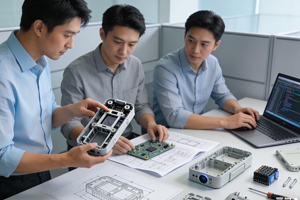
However, a mold shouldn’t be planned from a product file alone. The product needs a close look first. Skipping this step is one of the most common, costly mistakes hardware teams make.
Product Shape
Start with the part’s overall shape. Look for deep areas, sharp corners, thin walls, and tricky features. So these affect how plastic flows and how easily the part comes out. A rib with a 4:1 depth-to-width ratio, for instance, is far more likely to trap air or stick during ejection than a shallow one.
Wall Thickness
Try to keep wall thickness even, generally within 25% across the part. Big swings, however, cause uneven cooling. That raises the risk of sink marks and warping. Autodesk notes that thick spots take longer to cool and can warp as plastic sets. Most electronics housings run 1.5mm to 3mm thick, depending on the resin used.
Draft Angle
Draft is a small slope added to a wall so the part can pull free from the mold. Without enough draft, however, a part sticks during ejection, which can damage the surface or slow the whole run. Plan for at least 1 to 2 degrees on smooth surfaces, and up to 5 degrees on textured ones. Draft needs to shift with material, finish, depth, and shape, so review it during product design, not after.
Undercuts
An undercut is a feature that blocks the normal path used to pull a part free, like a snap-fit clip or a side hole. Some undercuts, however, need slides or other moving mold parts, which adds cost. Autodesk lists undercuts, draft, wall thickness, weld lines, sink marks, and fill behavior as the core factors in how easy a part is to mold. If your design has more than two or three undercuts, ask if it can be made simpler first.
Key Parts of Mold Design
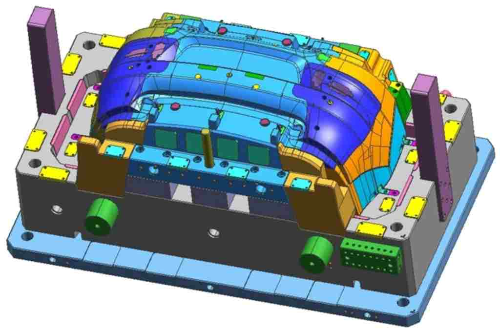
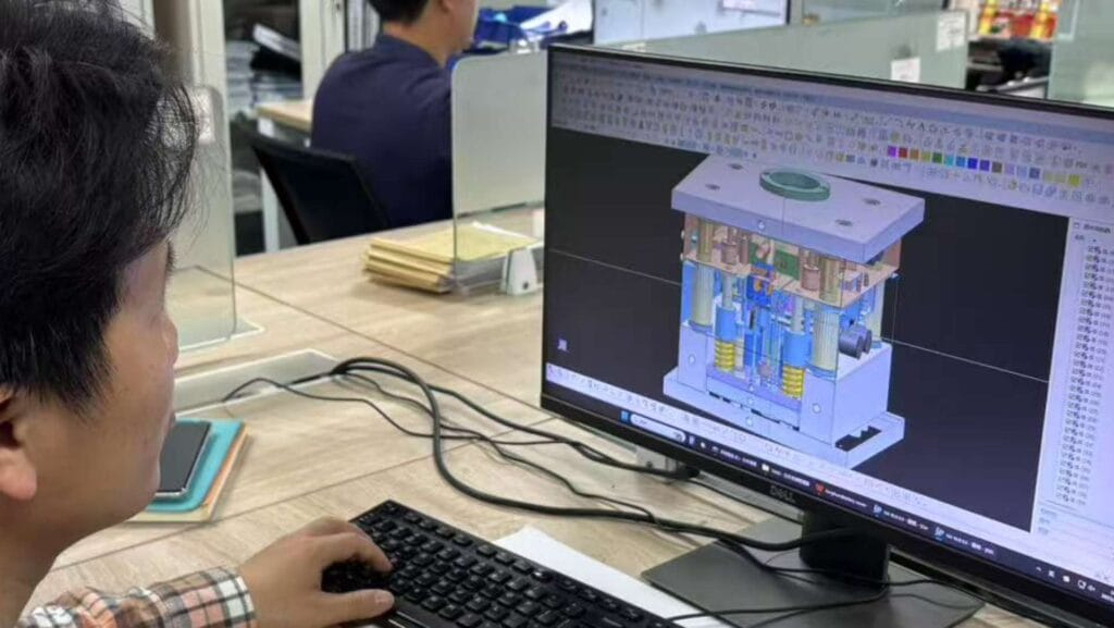
A mold is really a set of smaller systems. Each one has its own job:
- Cavity — Forms the outside shape of the part
- Core — Forms the inside shape
- Gate — Lets plastic enter the cavity
- Runner — Carries plastic toward the cavity
- Cooling system — Controls mold temperature
- Ejection system — Pushes the finished part out
- Venting — Lets trapped air escape
- Guide system — Keeps mold halves lined up
These systems, however, don’t work alone. They interact all the time. Gate placement affects how plastic enters the cavity. The cooling system affects how fast it sets, and so how long each cycle takes. Get one piece wrong, therefore, and it usually shows up as a defect somewhere else. OPD Design breaks all of this down in its guide to mold structure.
Mold Injection Design: Key Steps
The term mold injection design covers more than just drawing the mold in CAD. It includes several steps that stop costly surprises later on.
1. Review the Part
Check the product design first: shape, wall thickness, draft, ribs, bosses, and holes. So the goal is to catch issues before tooling starts. Fixing a wall-thickness problem now might cost an afternoon. Fixing it after the mold is cut can cost $5,000 to $50,000, plus weeks of delay.
2. Review Material Needs
Different plastics act differently in a mold. Material choice affects flow, cooling, shrink rate, strength, and finish, so pick it based on real performance needs, not habit or cost alone. ABS shrinks around 0.4–0.7%, while polypropylene can shrink 1–2.5%, a gap that alone can throw off your tolerances if it’s not planned for early.
3. Plan the Parting Line
The parting line is where the two mold halves meet. Its spot affects how the part looks, how it ejects, flash, and gate placement. So on products people will actually see, a poorly placed line can leave a seam right across a logo or a curved surface.
4. Plan Gates and Runners
The gate is where hot plastic enters the cavity. Its spot affects both fill and looks. The runner system carries plastic from the machine into the cavities. Additionally, its layout has to match the part and the batch size. So a poorly placed gate can leave a mark that customers will notice.
5. Plan Cooling
Plastic needs time to cool evenly before it’s safe to pull out. Cooling channels control mold temperature. A poor layout, however, raises cycle time or causes uneven shrink. In high-volume runs, even a two-second cut in cycle time can save tens of thousands of dollars.
6. Plan Ejection
The finished part has to leave the mold without damage, so place ejector pins with visible surfaces in mind. Marks from badly placed pins can show up right on the finished part.
The Mold Development Process
A clear process cuts down on mistakes and rework:
- Design review — Product shape and molding risks get checked
- DFM review — The part gets checked for how easy it is to build
- Mold planning — Parting line, gates, cooling, and ejection get mapped out
- Mold design — Detailed mold drawings get made
- Mold making — The mold parts get built
- Mold testing — The mold gets tested with real plastic
- Refinement — Problems get fixed where needed
- Production — The mold moves into full production
DFM, therefore, stands for “design for manufacturing.” It just means checking if a product can actually be built in a practical way, not just whether it looks right on screen.
Real-World Example: Portable Radio Detector

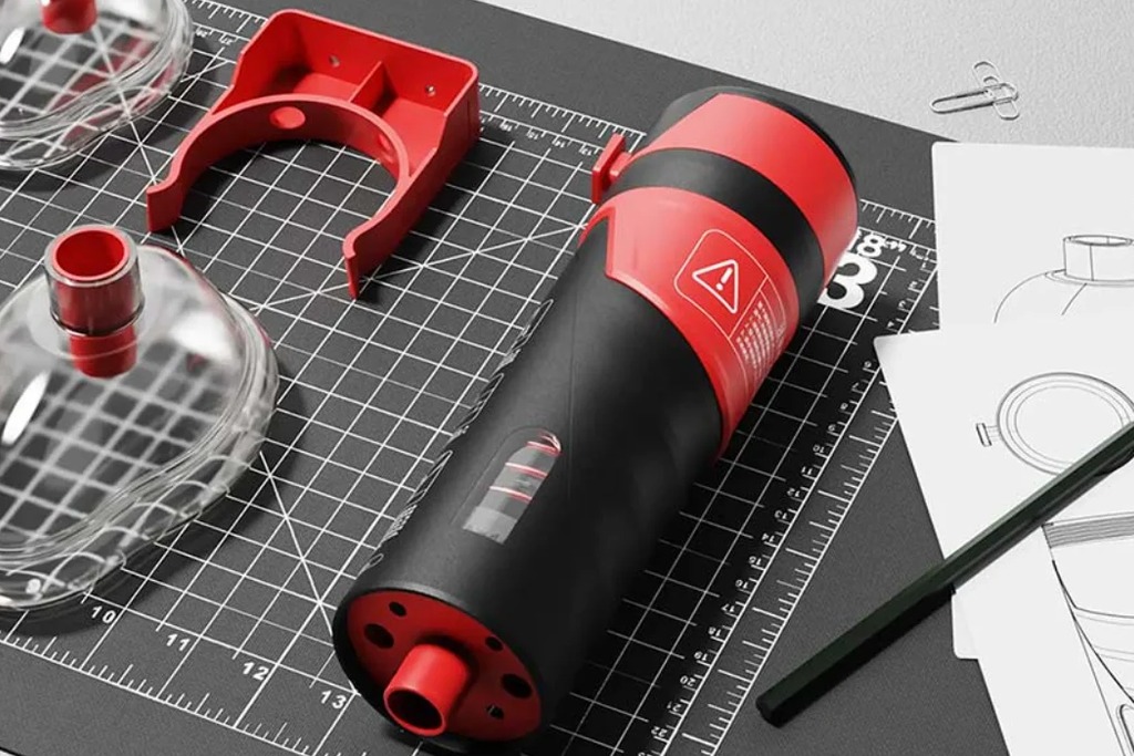
A recent project shows how mold work fits into a bigger process. The Portable Radio Detector went through prototyping and testing first. Then came mold design and development, then refinement, and only then mass production. So this shows why testing should happen before final tooling. Prototypes reveal issues while they’re still cheap to fix.
Common Problems to Avoid
Sink marks look like small dips near thick sections, where cooling runs uneven. Warping, however, happens when a part bends after ejection, usually from uneven cooling or shrink. A short shot means plastic doesn’t fully fill the cavity; flow, heat, pressure, material, and gate design can all play a part. Flash, however, is thin, stray plastic along a split line. It usually points to a fit issue or a process setting that’s off. Hard ejection often traces back to too little draft, though deep features and undercuts make it worse too.
How Prototyping Helps
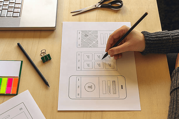
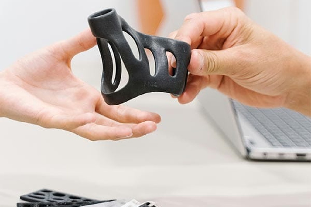
Prototyping lets your team test the design before you commit to full tooling. A prototype, for instance, checks size, fit, shape, function, handling, assembly, and surface detail. Additionally, it can also show if a design change is needed before mold work even starts. OPD Design offers prototyping, including 3D printing, CNC machining, and vacuum casting. Prototyping doesn’t replace mold testing, however, but it does give the team another, cheaper shot at catching problems early.
How to Choose an Injection Molding Partner
When you compare a plastic mold injection company, don’t judge them only on their ability to cut a mold. Instead, look at their whole process. A strong partner knows your product and its production needs. They should be able to walk you through design risks in plain terms, not jargon. Ask about their approach to DFM review, mold structure, material choice, parting line, gate location, cooling, ejection design, and production support. So this wider view helps you dodge the gap that often opens up between product design and real manufacturing.
Every product has different needs, too. For instance, a small enclosure might need a simple mold. A part with side holes or snap-fits may need a more complex ejection plan. The right approach depends on part shape, material, size, surface needs, volume, and assembly needs. Consequently, there’s no single layout that fits every product. That’s exactly why a design review should happen before the mold gets built, not after.
A Simple Pre-Tooling Checklist
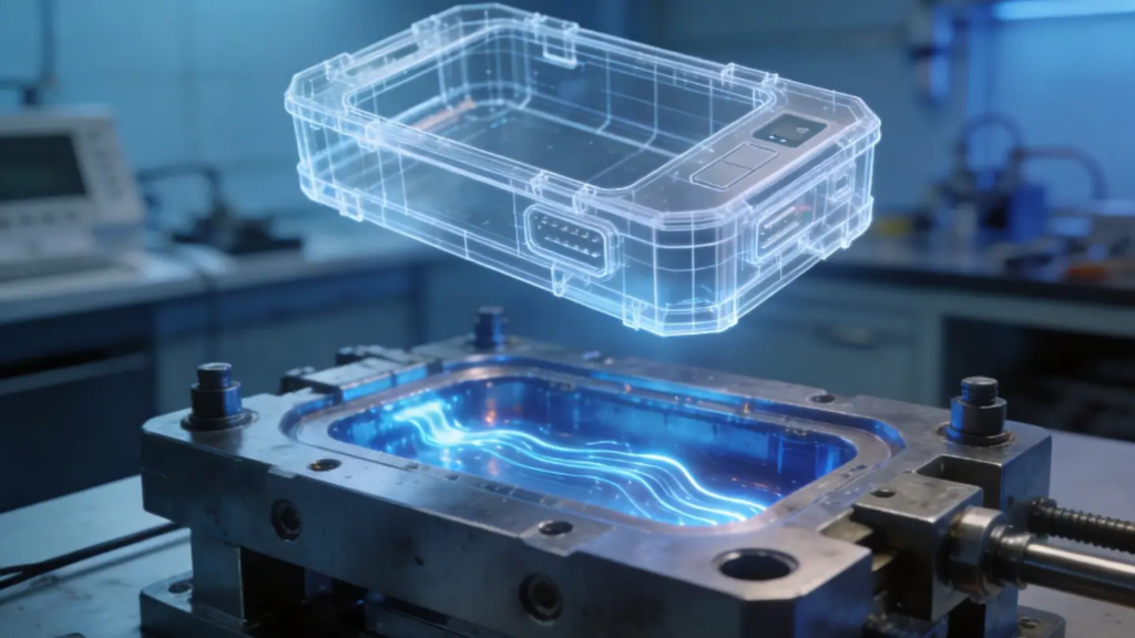
Before you approve a mold, check these points:
- Is the wall thickness fairly even?
- Are draft angles on all vertical walls?
- Are the undercuts truly needed?
- Is the parting line in a spot that won’t hurt looks?
- Are the gates in the right areas?
- Can trapped air escape the cavity?
- Is cooling planned for even heat control?
- Can the part leave the mold easily, without damage?
- Has the part been checked for DFM?
- Has the full design been reviewed before tooling begins?
So a simple checklist like this can catch most of the costly issues before they ever show up.
Ready to Review Your Mold Design?
Mold problems are almost always easier, and cheaper, to fix before tooling starts. Review the part design, material, draft, wall thickness, parting line, gates, cooling, and ejection before you move to tooling. OPD Design supports this whole process, from early design through mold work and into production.
Need help with your next plastic product? Contact OPD Design to talk through your needs.
Conclusion
Good injection mold design starts with good product planning, not the other way around. Instead, the mold has to match the part, the material, the batch size, and the final use. Wall thickness, draft, undercuts, gates, cooling, and ejection all deserve a close look before tooling begins.
A DFM review, therefore, catches problems early. Prototyping gives your team more time to test before you commit to a mold. Mold work shouldn’t happen on its own. It should connect to product design, engineering, prototyping, and manufacturing. With the right planning up front, teams cut design risk and build a clearer path to production.
Frequently Asked Questions
1. What is injection mold design?
It’s the process of planning the mold used to make a plastic part. That covers the cavity, core, gates, cooling, venting, and ejection system.
2. Why does mold design matter so much?
It affects part quality, speed, cooling, fill, and ejection. Good planning up front also cuts down on costly changes later.
3. What does mold design for injection molding involve?
That’s mold design for injection molding in practice — building a mold that reliably fills, cools, and releases a part, run after run, without defects.
4. What is mold injection design, exactly?
It’s planning how the mold handles plastic flow, cooling, and part release before a single piece gets built.
5. When should mold design start?
During product development, not after. Early review gives your team more time to fix problems while changes are still cheap.
6. Can prototypes really help before mold work begins?
Yes. Prototypes let teams test size, fit, function, and shape before tooling starts. That catches costly mistakes while they’re still cheap to fix.