
A prototype can work perfectly during a product demonstration and still fail in the hands of customers.
The difference is often time, variation, and environment.
A customer may press the same button thousands of times, charge the battery every day, leave the product in a hot car, clean it with alcohol, drop it onto a hard floor, carry it through rain, or store it for months before use. Production also introduces variation in materials, dimensions, suppliers, mold cavities, assembly force, soldering, adhesives, and firmware configuration.
Product reliability testing evaluates whether a product can continue to perform its required functions for a defined period under defined conditions. It helps a development team find weak components, unsuitable materials, fragile structures, unstable interfaces, and uncontrolled manufacturing processes before those problems become warranty claims, returns, safety incidents, or brand damage.
However, reliability is not proven by completing a generic checklist. A meaningful test program must connect the product’s intended use with measurable requirements, realistic failure mechanisms, representative samples, justified stress levels, and documented pass/fail criteria.
This guide explains how to build that connection for consumer electronics, IoT devices, wearables, beauty devices, healthcare products, children’s products, and other custom hardware.

What You Need to Know in 30 Seconds
- Reliability testing asks whether the product will continue to meet its requirements over time and use—not only whether it works once.
- Functional testing, compliance testing, quality control, and reliability testing overlap, but they answer different questions.
- Test conditions should come from the intended user, environment, life expectancy, transport route, foreseeable misuse, and known failure mechanisms.
- Early EVT testing should expose design weaknesses; DVT should validate the controlled production-intent design; PVT should confirm that the production process can reproduce it.
- Sample size should be justified statistically and technically. A few passing units may find obvious weaknesses but rarely demonstrate a reliability claim with high confidence.
- Accelerated life testing is useful only when the applied stress accelerates the same failure mechanism expected in normal use and the relationship can be modeled.
- Every failure should be contained, reproduced, analyzed, corrected, and retested. A test report without a failure-closure process has limited value.
- Passing a reliability test does not mean a product is failure-proof, certified for every market, or suitable for uses outside its defined scope.
What Is Product Reliability Testing?
Reliability is usually expressed as the probability that an item will perform a required function, under stated conditions, for a stated period of time.
Each part of that definition matters:
- Probability recognizes that products and processes contain variation.
- Required function means success must be defined through measurable performance criteria.
- Stated conditions define the use, storage, transport, maintenance, and environmental boundaries.
- Stated period may be calendar time, operating hours, duty cycles, charging cycles, button presses, opening cycles, or another relevant measure of life.
The NIST Engineering Statistics Handbook distinguishes quality from reliability by describing quality as conformance at the start of use and reliability as how that performance changes over time. In practical terms, final inspection provides a snapshot; reliability testing studies the longer motion picture. See NIST’s explanation of quality versus reliability.
For example, a smart dispenser may pass its initial functional test because the motor rotates and the correct volume is delivered. A reliability program asks additional questions:
- Will delivery accuracy remain within specification after thousands of cycles?
- Will gear wear, lubricant migration, motor heating, battery aging, or sensor drift change performance?
- Will the enclosure, seal, and user interface survive cleaning and humidity?
- Will normal production variation create units that fail earlier than the engineering samples?
Reliability testing is therefore not a single laboratory event. It is a development process that links requirements, risk analysis, prototype builds, testing, failure analysis, engineering changes, pilot production, and field feedback.
Reliability Testing vs. Functional Testing, Compliance, and Quality Control
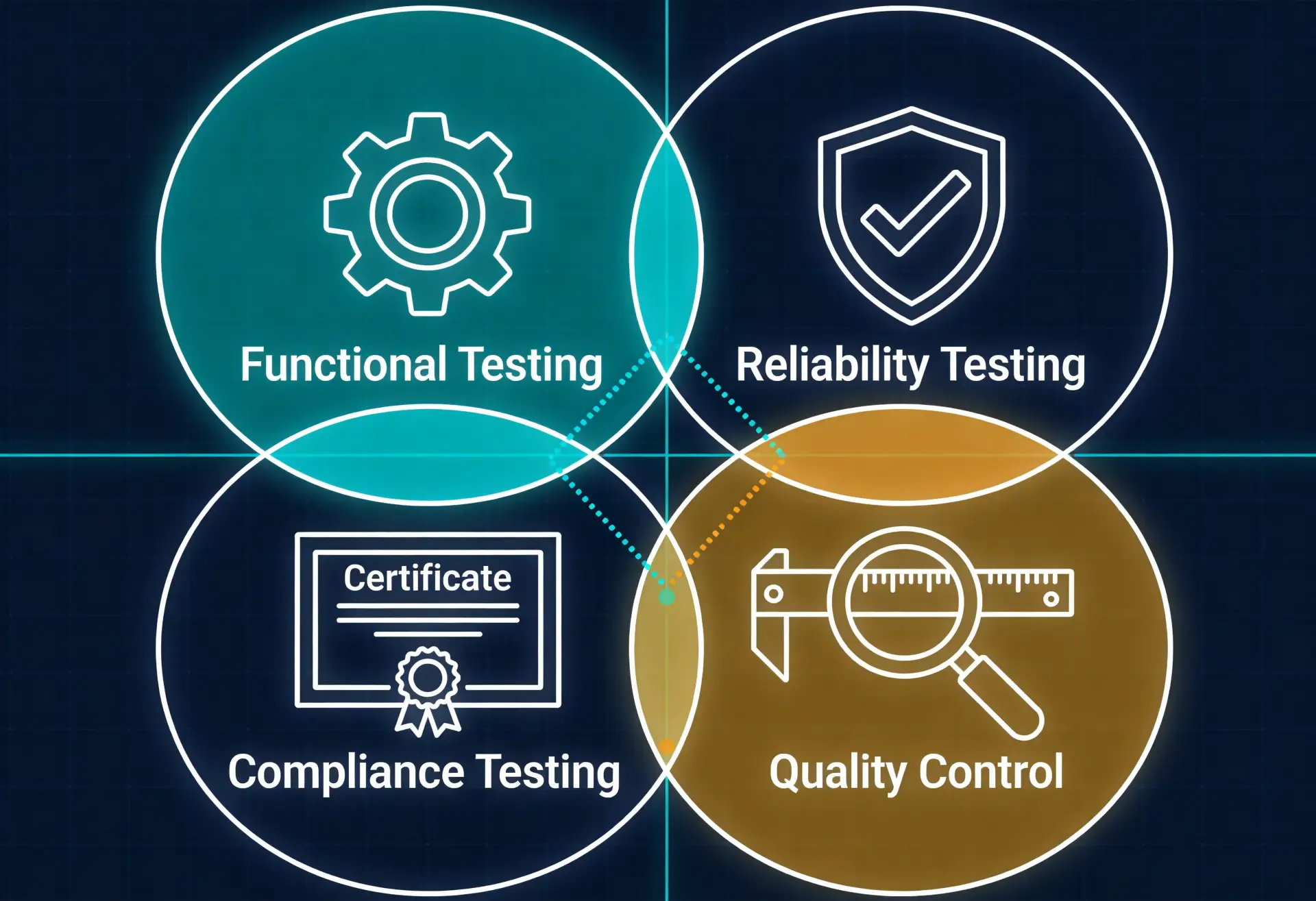
Teams often use these terms interchangeably, which can create serious gaps in a validation plan.
| Activity | Primary Question | Typical Evidence | What It Does Not Prove by Itself |
|---|---|---|---|
| Functional testing | Does the product perform the required function now? | Output, accuracy, response, power, connectivity, control behavior | Continued performance over life or stress |
| Reliability testing | Does the product continue to meet requirements for the defined life and conditions? | Lifecycle, environmental, durability, degradation, and failure data | Regulatory approval or zero future failures |
| Compliance testing | Does the defined configuration meet an applicable regulation or standard? | Accredited or competent laboratory reports, technical files, declarations, certificates where applicable | Good user experience or reliability beyond the standard’s scope |
| Quality control | Does a produced unit conform to the approved specifications and process limits? | Incoming, in-process, and final inspection data; process and yield records | That the approved design has an adequate lifetime |
| Usability validation | Can intended users perform critical tasks safely and effectively? | Observed task performance, use errors, feedback, and risk evidence | Mechanical or electronic life unless included in the protocol |
A product may pass electrical safety and EMC testing but have a hinge that breaks after three months. It may survive a lifecycle test but fail regulatory labeling requirements. It may have a strong design but still leave the factory with defects because the production process is unstable.
These disciplines should inform one another, but none should be treated as a substitute for the others.
Why Reliability Problems Often Appear Late
Many hardware failures are not visible during a short demonstration. They emerge when several small effects accumulate.
Prototype Materials Differ from Production Materials
A printed “ABS-like” enclosure may not reproduce the creep, impact resistance, chemical resistance, UV behavior, shrinkage, or fatigue performance of the selected injection-molding resin. A hand-cast seal may not represent the compression consistency of a molded production gasket.
Nominal Fit Hides Manufacturing Variation
One carefully assembled prototype can sit near the center of every tolerance. Production combines parts from different cavities, lots, suppliers, operators, and environmental histories. Worst-case combinations may create excessive force, insufficient compression, noise, gaps, leakage, or premature wear.
Short Tests Miss Cumulative Damage
Repeated loads can initiate cracks, loosen fasteners, polish contact surfaces, wear coatings, fatigue wires, compress foam, change spring force, or degrade adhesives. The unit may look normal until a threshold is crossed.
Environmental Stresses Interact
Humidity may affect a material differently after thermal cycling. A drop may damage a seal without causing immediate functional failure. Cleaning fluid may enter through a crack created by repeated bending. Sequential stresses can reveal interactions that isolated tests miss.
Electronics and Firmware Have Long-Duration Failure Modes
Memory leaks, counter overflow, reconnection failures, storage corruption, sensor drift, timing problems, and thermal behavior may appear only after long operation, repeated power interruption, or unusual state transitions.
The Factory Changes the System
Production tooling, automated soldering, adhesives, torque tools, fixtures, test limits, packaging, and operator methods can all change the product compared with an engineering build. Reliability must be confirmed on controlled production-intent configurations and supported by process validation.
Start with a Reliability Requirement, Not a Test Machine
“Perform a drop test” is not yet a reliability requirement.
A useful requirement connects use and risk to measurable evidence. It should define:
- The required function or performance limit
- The operating, storage, and transport conditions
- The intended life or number of cycles
- The test method and product configuration
- The measurement points before, during, and after testing
- The acceptance criteria
- The sample and statistical rationale
- Any allowed maintenance or replacement
Consider a handheld connected product. “The product must be durable” is too vague. A more useful design input might specify that, after a defined number of drops from stated heights and orientations onto a defined surface, the production-intent product must retain enclosure integrity, electrical safety, charging, wireless connectivity, critical accuracy, and any required ingress protection. The actual heights, orientations, sample quantity, conditioning, and limits must come from the intended-use environment, risk analysis, applicable standards, and product requirements—not from a generic blog post.
This distinction prevents a common mistake: selecting a familiar test and then inventing a justification for it afterward.
Build a Product Life-Cycle Profile
Before choosing test methods, map what the product experiences from manufacture to end of life.
Manufacturing and Assembly
- Soldering and rework temperatures
- Fastener torque and press-fit loads
- Adhesive cure and fixture time
- Ultrasonic welding or heat staking
- Cleaning, handling, and electrostatic exposure
- Functional test and calibration
Storage and Distribution
- Warehouse temperature and humidity
- Stacking and compression
- Truck, air, sea, and parcel vibration
- Drops, impacts, and repeated handling
- Low pressure during air transport where relevant
- Storage duration and battery state of charge
Installation and First Use
- Unboxing and assembly
- Mounting loads and connector insertion
- Pairing, account setup, firmware update, and calibration
- User interpretation of instructions
Normal Operation
- Duty cycle and operating hours
- Force, load, pressure, speed, and motion
- Charging and discharging
- Temperature rise and cooling
- Wireless connection and data transfer
- Cleaning, sweat, cosmetics, oils, or chemicals
- Indoor, outdoor, mobile, wearable, or wet-area exposure
Foreseeable Misuse and Abnormal Events
- Wrong orientation or over-force
- Blocked airflow
- Repeated rapid operation
- Cable pulling and connector misuse
- Drops and spills
- Interrupted power or network access
- Use near the stated environmental limits
Maintenance and End of Life
- Filter, battery, accessory, or consumable replacement
- Cleaning and disinfection
- Firmware and software support
- Service access and reassembly
- Performance degradation and retirement criteria
The resulting life-cycle profile becomes the basis for the reliability risk analysis and test matrix.
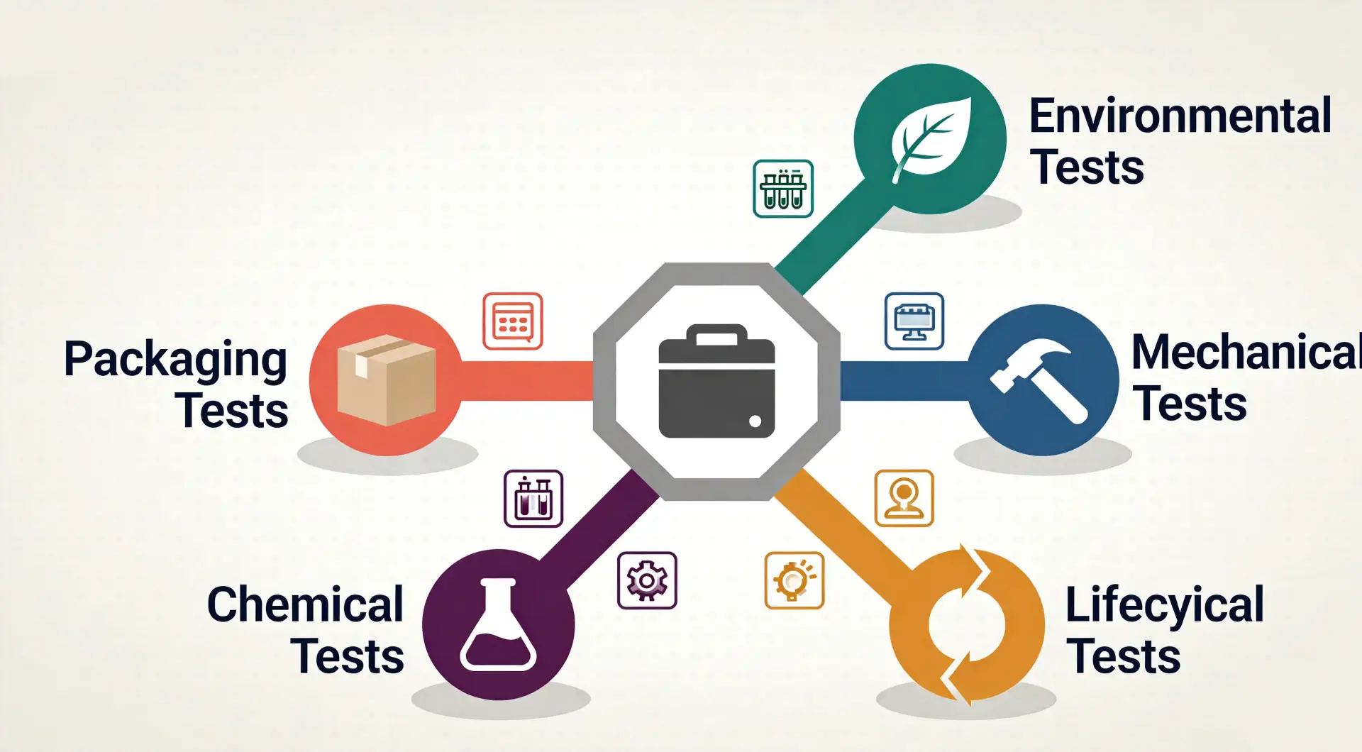
Main Types of Product Reliability Testing
The correct combination depends on product architecture and intended use. Not every product needs every test, and the same test severity should not be copied across unrelated categories.
1. Functional Endurance and Cycle Testing
Functional endurance tests repeatedly operate mechanisms and interfaces to reveal wear, fatigue, drift, loosening, and intermittent behavior.
Examples include:
- Buttons, switches, triggers, and touch controls
- Hinges, latches, doors, and adjustment mechanisms
- Connectors, charging ports, and cable strain relief
- Pumps, valves, fans, motors, gears, and actuators
- Casters, bearings, sliders, locks, and springs
- Consumable insertion and removal
- Battery charging and discharging
The protocol should reproduce the relevant load, speed, orientation, dwell time, duty cycle, and user interaction. Measurements should be taken at meaningful intervals rather than only at the end. A device that still moves after 20,000 cycles may nevertheless have unacceptable noise, output drift, temperature rise, backlash, leakage, or operating force.
2. Mechanical Shock, Drop, Impact, and Compression
Mechanical testing evaluates whether the product and its internal components can tolerate handling, accidents, transport, and operating loads.
Possible tests include:
- Controlled free-fall drops
- Repeated drops from realistic user heights
- Impact to vulnerable surfaces
- Shock pulses while mounted
- Topple and tip-over
- Static compression or stacking
- Torsion, bending, and pull forces
- Strain-relief and connector-load tests
3. Vibration Testing
Vibration can loosen screws, fatigue solder joints and wires, create connector fretting, damage batteries, generate noise, and expose structural resonances.
Testing may use sinusoidal vibration, random vibration, or a measured field profile. IEC 60068-2-64 addresses broadband random vibration and emphasizes evaluating functional or structural degradation under specified dynamic loads.
Random laboratory vibration is not automatically representative of every transport route or operating environment. The axes, mounting condition, power state, spectral density, frequency range, duration, and functional monitoring should be justified.
4. Temperature and Thermal-Cycle Testing
High and low temperatures affect materials, dimensions, batteries, displays, lubricants, seals, sensors, adhesives, plastics, and electronic components. Temperature changes can also create condensation and fatigue interfaces through different coefficients of thermal expansion.
A reliability plan may include:
- High- and low-temperature operation
- High- and low-temperature storage
- Temperature cycling
- Thermal shock where relevant
- Repeated powered operation at temperature limits
- Performance measurements during exposure
- Recovery and post-conditioning inspection
5. Humidity, Condensation, Corrosion, and UV Exposure
Humidity can reduce insulation resistance, corrode conductors, swell hygroscopic materials, affect adhesives, fog optics, and promote leakage. Condensation may be more severe than steady humidity for some products. Salt, sweat, pollution, and cleaning residue can further accelerate corrosion.
Testing may include:
- Damp heat at constant temperature
- Cyclic temperature and humidity
- Condensation exposure
- Salt mist or application-specific corrosive environments
- Artificial sweat for body-contact products
- UV weathering for outdoor products
- Post-exposure electrical, cosmetic, sealing, and material checks
6. Dust and Water Ingress Testing
An enclosure can fail ingress testing because of gasket compression, part warpage, cable entry, membrane bonding, vent selection, fastener torque, surface finish, or damage from earlier tests.
Ingress validation should control:
- Production-intent materials and seals
- Fastener and assembly process
- Port, door, vent, and connector states
- Preconditioning and aging
- Water pressure, flow, angle, duration, and temperature
- Dust type, vacuum condition, and exposure
- Functional and safety checks after the test
IP codes are defined through applicable standards such as IEC 60529; they should not be treated as a general synonym for “waterproof.” An IP rating applies to a defined enclosure configuration and test condition. It does not automatically cover every liquid, depth, duration, cleaning method, wear state, or damaged product.
7. Material, Surface, and Chemical Resistance
Reliability is often decided at the surface where the product meets the user and environment.
Relevant exposures may include:
- Skin oils, sweat, sunscreen, cosmetics, and sebum
- Alcohol, disinfectants, detergents, and household cleaners
- Fuels, lubricants, and industrial chemicals
- Abrasion, scratching, and repeated wiping
- Adhesion of paint, printing, coating, plating, and labels
- Color change, gloss change, cracking, swelling, tackiness, and odor
The chemical list should come from realistic use and cleaning instructions. A material coupon can support early screening, but the final test may need the complete production stack: substrate, texture, primer, coating, print, adhesive, curing process, geometry, and residual stress.
8. Electrical, Power, Battery, and Connectivity Reliability
Electronic products need more than a successful power-on test. Depending on the architecture, reliability work may include:
- Power cycling and brownout recovery
- Input-voltage and load boundaries
- Charging interruption and restart
- Battery cycle life and storage behavior
- Connector wear and contact resistance
- Long-duration operation at thermal load
- Sensor drift and calibration stability
- Wireless reconnection, roaming, interference, and weak-signal behavior
- Firmware update interruption and recovery
- Data integrity after power or network loss
- Clock, counter, memory, and storage endurance
Electrical safety, EMC, radio, and battery compliance may introduce separate mandatory test requirements. Reliability testing should be coordinated with those programs so that the hardware, firmware, battery, charger, cable, and accessories remain one traceable configuration.
9. Packaging and Distribution Testing
The customer receives a packaged-product system, not an isolated device.
Packaging testing can expose damage caused by shock, vibration, compression, temperature, humidity, abrasion, and repeated handling. The International Safe Transit Association explains that its 3-Series protocols simulate damage-producing motions, forces, conditions, and sequences in transport environments. ISTA also advises retesting when the product, package, or process changes in a way that may affect performance.
A packaging test should evaluate more than whether the outer carton remains intact. Acceptance criteria may include:
- Product function and calibration
- Cosmetic condition
- Internal movement and accessory retention
- Seal and connector condition
- Display, lens, and surface protection
- Label legibility and package closure
- Customer-ready presentation
10. Combined and Sequential Stress Testing
Real failures often occur because stresses interact. A useful sequence might condition a product through temperature and humidity, complete mechanical cycling, apply drop or vibration, and then repeat ingress and functional checks.
The order matters. Sequential testing can represent accumulated life, but it can also make root-cause analysis harder. A strong plan may use some dedicated samples to isolate mechanisms and other samples for combined-use sequences.
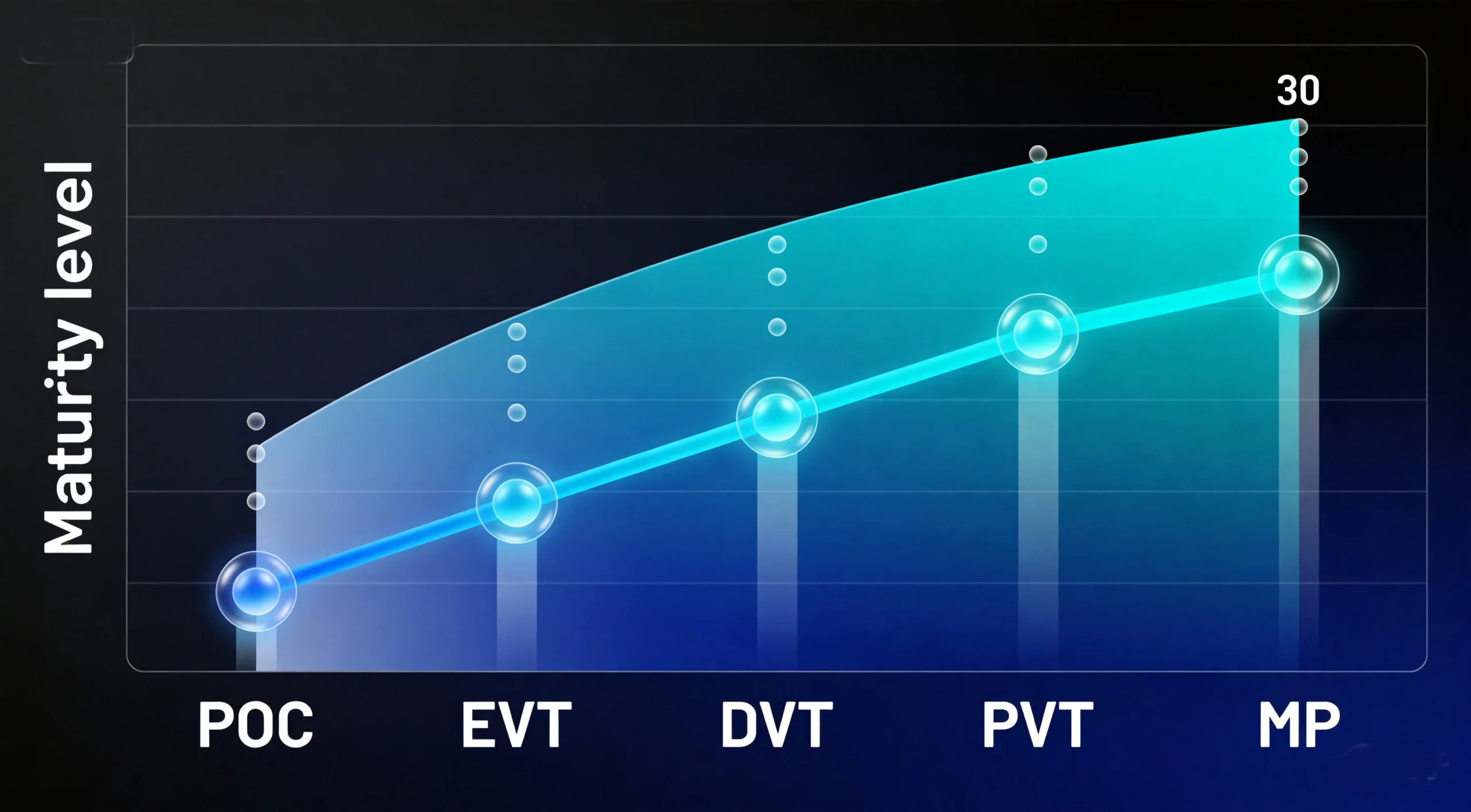
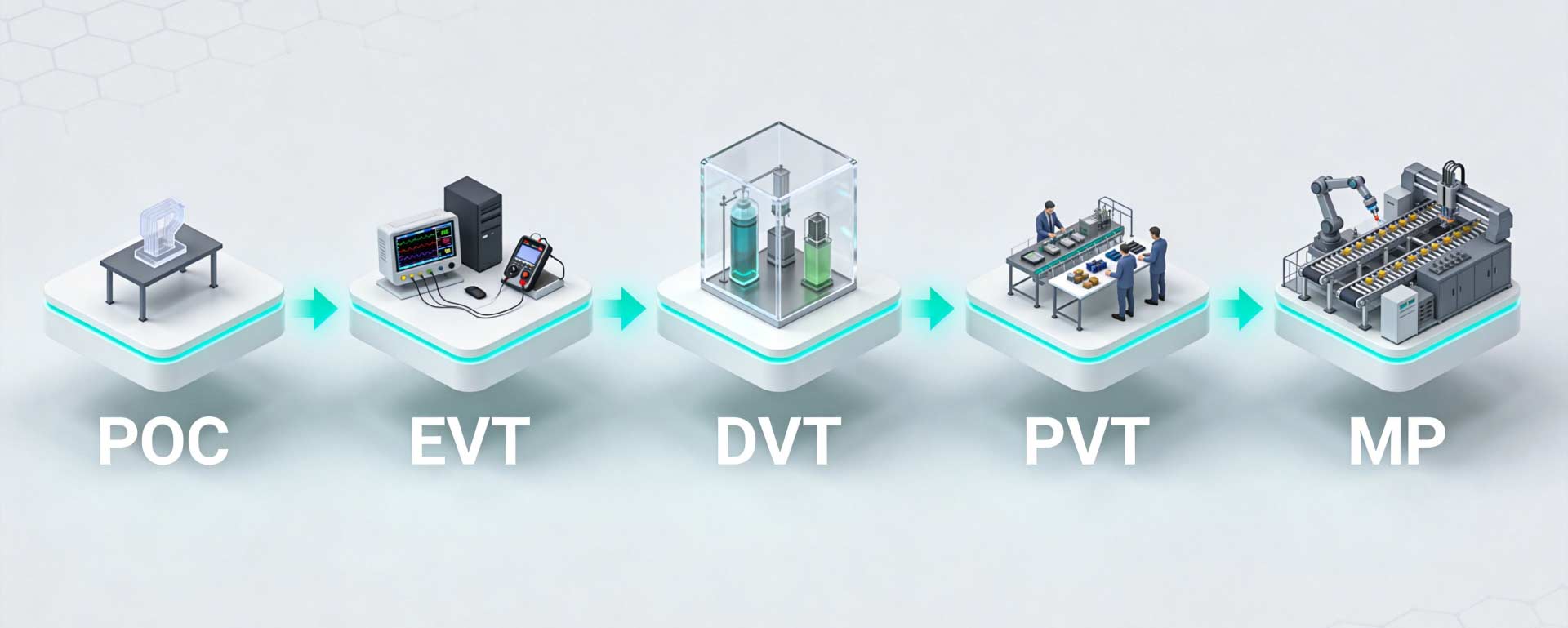
Reliability Testing Across POC, EVT, DVT, PVT, and Mass Production
Reliability should mature with the product rather than being postponed until the end.
| Development Stage | Reliability Objective | Appropriate Evidence | Main Caution |
| POC | Identify whether a high-risk principle is feasible | Focused mechanism, material, thermal, power, or sensor experiments | Do not claim complete-product life from a proof of concept |
| EVT | Find design weaknesses and establish engineering margins | Targeted stress, endurance, environmental screening, failure analysis, and repeated builds | Prototype processes and materials may limit conclusions |
| DVT | Validate the controlled production-intent design against requirements | Full reliability matrix, production materials, representative tooling, complete hardware and firmware | Test the released configuration, not a mixture of revisions |
| PVT | Confirm the intended process can reproduce the validated design | Pilot units from production tools, operators, suppliers, work instructions, fixtures, and inspections | A small hand-selected batch does not prove stable production |
| MP | Monitor reliability and control changes | Yield, audit tests, ongoing reliability tests, returns, failure analysis, supplier data, and field performance | Do not stop learning after launch |
POC: Test the Risk That Could End the Project
Early testing should focus on the assumption most likely to invalidate the concept: a seal, pump, optical path, antenna, thermal system, battery, sensor, material, or mechanism. It is usually wasteful to run a full cosmetic product through a broad matrix while the technical architecture remains uncertain.
EVT: Discover, Diagnose, and Improve
EVT reliability testing is often exploratory. Engineers may intentionally test beyond the expected boundary to identify weak points and understand margins. The purpose is not only to pass; it is to learn why and how the design fails while changes remain relatively inexpensive.
DVT: Validate the Production-Intent Design
DVT requires controlled samples, approved materials, traceable CAD and BOM revisions, defined firmware, calibrated equipment, and approved procedures. The test matrix should cover the intended life, environments, critical risks, compliance interfaces, packaging, and foreseeable use.
PVT: Validate Repeatability
PVT units should come from the intended production line using production tooling, processes, operators, materials, fixtures, and inspection methods. Reliability sampling during or after the pilot run helps identify variation that engineering builds may not represent.
Mass Production: Continue Reliability Surveillance
Ongoing reliability testing, process audits, supplier controls, return analysis, and change qualification help confirm that performance remains stable. A design or supplier change that seems minor can alter material properties, sealing, fatigue, thermal behavior, EMC, or chemical resistance.
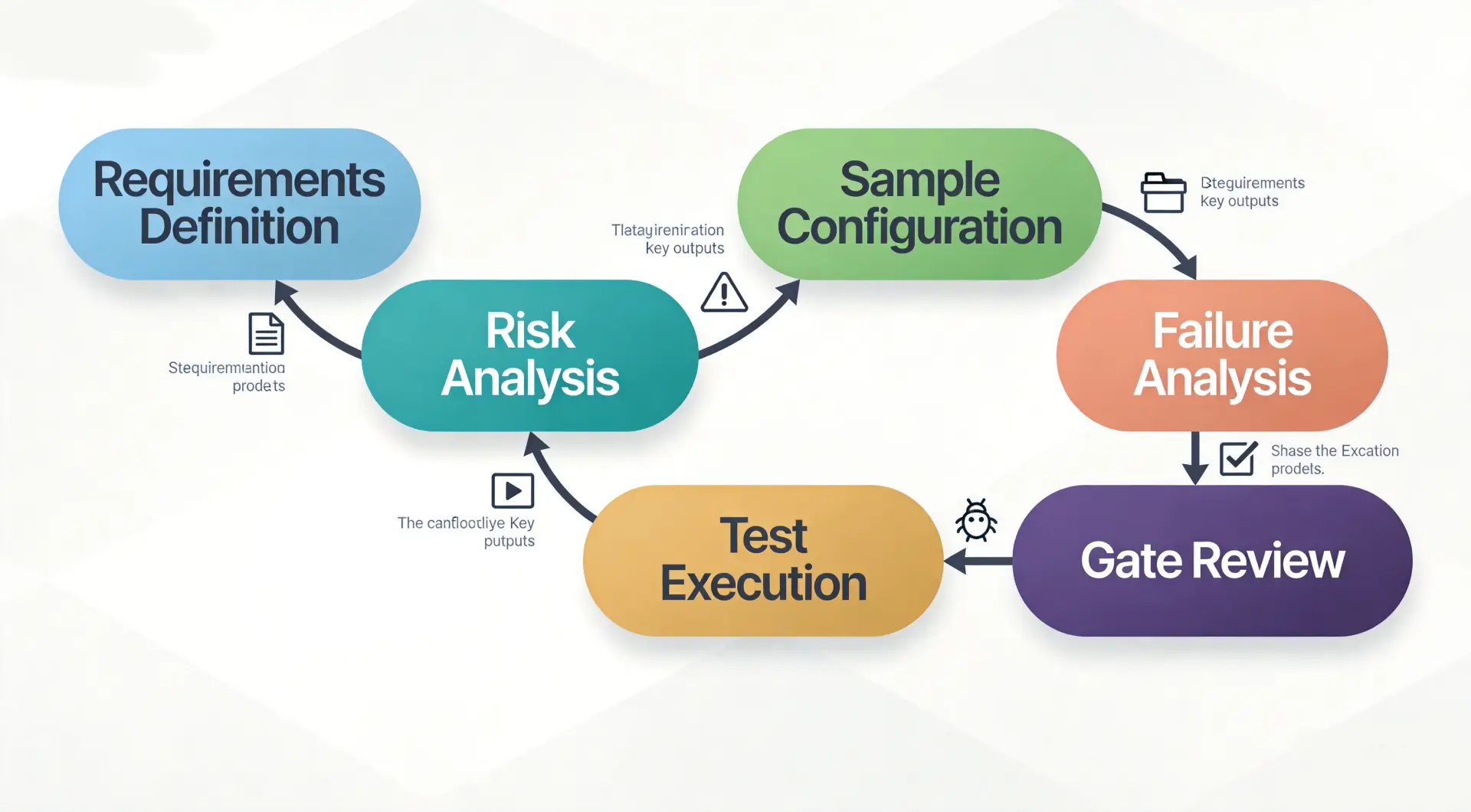
How to Create a Product Reliability Test Plan
Step 1: Define Intended Use and Reliability Goals
Document the target user, operating environment, duty cycle, storage, transport, maintenance, useful life, warranty context, and critical functions. Translate these into measurable targets.
Step 2: Review Applicable Requirements
Identify product-category standards, target-market regulations, customer requirements, platform or retailer requirements, internal engineering specifications, and supplier limits. Use current editions and confirm applicability with qualified specialists.
Step 3: Perform Risk Analysis
Use tools such as Design FMEA, fault-tree analysis, hazard analysis, tolerance analysis, and lessons from similar architectures to identify:
- Failure mode
- Cause and mechanism
- Effect on the user or product
- Severity and likelihood
- Detection opportunity
- Prevention and verification control
The test matrix should prioritize high-severity and high-uncertainty risks, not only tests that are easy to run.
Step 4: Define the Use and Stress Model
Convert field conditions into loads, cycles, temperatures, humidity, chemicals, power states, and sequences. Document why each laboratory stress represents the expected life or a known acceleration relationship.
Step 5: Select the Product Configuration
Record:
- CAD and drawing revision
- BOM and approved substitutions
- PCB and assembly revision
- Firmware and software version
- Tool, cavity, supplier, and material lot
- Assembly process and deviations
- Accessories, charger, cable, packaging, and consumables
Without configuration control, a passing report may not apply to the product being manufactured.
Step 6: Define Sample Size and Allocation
Allocate samples according to the decisions the test must support. Consider:
- Required reliability and confidence
- Expected failure distribution
- Allowed failures
- Test duration or cycles
- Destructive versus non-destructive testing
- Product variation, lots, cavities, and suppliers
- Dedicated versus sequential stress samples
- Control samples
- Retest and failure-analysis needs
NIST’s guidance on planning a reliability assessment test emphasizes that sample quantity and duration depend on the assumed model, the conclusion to be drawn, and the acceptable decision risk. There is no universal sample count for all products.
Step 7: Write the Procedure and Acceptance Criteria
For each test, define:
- Objective and linked requirement
- Equipment and calibration status
- Sample mounting and orientation
- Preconditioning
- Stress level, duration, cycles, and sequence
- Product operating state
- Monitoring during the test
- Measurements and inspection intervals
- Allowed maintenance
- Pass, fail, and invalid-test criteria
- Safety controls and stop conditions
- Data and photo requirements
“No visible damage” is rarely sufficient. The product may need to meet dimensional, electrical, functional, safety, cosmetic, noise, force, accuracy, sealing, or data-integrity limits.
Step 8: Run a Baseline Before Stress
Measure each unit before testing. Baseline data makes it possible to identify drift, degradation, and unit-to-unit differences. Photograph critical areas and record serial numbers, configuration, initial performance, and any existing defects.
Step 9: Analyze Every Failure
A failed sample is not just a red cell in a spreadsheet. The team should:
- Protect people and stop unsafe testing.
- Preserve logs, measurements, configuration, and physical evidence.
- Determine whether the event is a product failure, fixture failure, procedural deviation, or invalid sample.
- Reproduce the failure when appropriate.
- Identify the physical and systemic root causes.
- Contain affected designs, materials, lots, or processes.
- Implement corrective action.
- Verify the correction and run relevant regression tests.
- Update risks, drawings, specifications, work instructions, and controls.
Simply replacing the failed part and continuing the test may erase the evidence needed to prevent recurrence.
Step 10: Approve the Gate with Residual Risk Visible
The final report should show:
- Requirements covered and not covered
- Sample configuration and traceability
- Procedures and deviations
- Raw and summarized results
- Failures, root causes, and corrective actions
- Retest and regression evidence
- Open issues and owners
- Statistical limitations
- Approved residual risks
- Recommendation for the next development stage
A pass/fail summary without these details can create false confidence.
How Many Samples Are Needed for Reliability Testing?
There is no honest universal answer.
Sample size depends on what the team wants to learn or demonstrate. Three prototypes may be useful for exposing an obvious mechanical weakness, comparing two concepts, or debugging a fixture. They usually do not provide strong statistical confidence that a production population will meet a specified reliability target.
For a simple one-shot demonstration with zero failures, independent samples, equal exposure, and a binomial model, the required sample count can be estimated as:
n = ln(1 − confidence) / ln(target reliability)
For example, demonstrating 90% reliability at 90% confidence with zero failures requires 22 successful samples after rounding up. This example does not automatically demonstrate a five-year product life; every sample must complete the defined mission or test exposure, and the model assumptions must be appropriate.
Real hardware programs may require more complex methods because:
- Products accumulate operating time or cycles.
- Units may be removed before failure, creating censored data.
- Failure rates change with age.
- Several failure modes exist.
- Samples come from different lots or cavities.
- Accelerated stresses require a life-stress model.
- Repairable systems differ from non-repairable products.
NIST notes that highly reliable products can be difficult to evaluate because meaningful precision depends strongly on observed failures, not merely the number of units placed on test. See its discussion of the lack-of-failures problem.
A reliability engineer or statistician should help design tests that support important quantitative claims, warranty decisions, safety decisions, or regulated submissions.
Accelerated Life Testing vs. Overstress Testing
These methods are related but should not be confused.
Accelerated Life Testing
Accelerated life testing increases a stress—such as temperature, voltage, load, humidity, or cycling rate—to produce the same relevant failure mechanism sooner. Data from multiple stress conditions may be fitted to a justified acceleration model and projected to normal use.
NIST’s accelerated life testing guidance explains that the goal may be to understand how stress accelerates failure and use that relationship to project performance under use conditions.
An invalid acceleration can create misleading conclusions. Excessive heat may melt a polymer even though field failures are caused by fatigue. Cycling a mechanism too quickly may remove realistic dwell time, introduce artificial heating, or change lubrication behavior. Raising voltage may activate a failure mode that cannot occur in the intended circuit.
Overstress or Limit Testing
Overstress testing intentionally approaches or exceeds expected boundaries to find design weaknesses, compare margins, or support reliability growth. It can be extremely useful during EVT, but results should not automatically be converted into a life claim.
The key question is:
“Are we discovering a weakness, validating a requirement, or estimating life?”
Each objective needs a different protocol and interpretation.
A Hypothetical Reliability-Test Example
Consider a hypothetical rechargeable handheld beauty device intended for frequent bathroom use.
The first functional prototype powers on, heats correctly, connects to an app, and looks close to the design render. A reliability review identifies several risks:
- Repeated thermal expansion may loosen the heater assembly.
- Cosmetic coating may react with skincare products and alcohol cleaning.
- A charging-port seal may lose compression after repeated insertion.
- Drops may crack an internal mounting boss without immediate external damage.
- Condensation may affect a sensor after the product cools.
- Firmware may fail to reconnect after interrupted charging and a network outage.
Instead of ordering one generic “reliability test,” the team creates linked tests:
- Heater cycles with temperature, power, and output measurements at intervals
- Port insertion cycles followed by sealing and contact-resistance checks
- Chemical exposure on production coating and printed markings
- Temperature-humidity cycling with powered functional checks
- Drops in defined orientations followed by internal inspection, safety, charging, and sealing tests
- Repeated power, charging, firmware-update, and reconnection state transitions
- Packaged-product distribution testing on final packaging
During EVT, a drop creates an internal crack but the unit still works. The team changes the boss geometry and material transition, then repeats the targeted test. During DVT, production-intent samples complete the approved matrix. During PVT, units from different tooling cavities and production lots are sampled to confirm that assembly variation does not reintroduce the problem.
This example is hypothetical. It illustrates how one successful prototype becomes a risk-based reliability program; it does not represent a disclosed OPD client project or a universal test matrix for beauty devices.
Common Product Reliability Testing Mistakes
Copying a Competitor’s Test Specification
Two visually similar products can have different materials, architectures, markets, duty cycles, claims, and risks. A competitor’s public specification may provide context, but it cannot replace your own requirements and standards review.
Testing Too Late
If the first serious drop, thermal, seal, or lifecycle test occurs after production tooling is complete, a failure may require expensive mold, PCB, supplier, or certification changes.
Testing Non-Representative Samples
A hand-finished prototype can support engineering learning but may not validate production material, tooling, tolerances, assembly, coating, or firmware. Every report should state what is and is not representative.
Using Arbitrary Severities
More stress is not always better. Unrealistic stress can create irrelevant failures; insufficient stress can miss real ones. Conditions must connect to field exposure, a recognized method, or a documented engineering rationale.
Declaring Success from a Small Number of Passes
A few passing units can establish feasibility, but statistical claims require a sample and model appropriate to the claimed reliability and confidence.
Ignoring Degradation Until Final Failure
Measure changes in force, noise, current, output, accuracy, temperature, leakage, appearance, resistance, or connectivity. Degradation trends can reveal a failure mechanism before total failure.
Mixing CAD, BOM, and Firmware Versions
If samples contain different parts or software, the results may not apply to any released configuration. Traceability is part of reliability evidence.
Retesting Only the Corrected Feature
A stronger boss may move stress into another area. A new gasket may increase assembly force. A firmware fix may affect battery life. Corrective action requires targeted confirmation and relevant regression testing.
Treating a Laboratory Pass as a Market Claim
Reliability evidence supports only the product, configuration, conditions, life, and acceptance criteria actually evaluated. Marketing language, warranty terms, regulatory claims, and instructions should remain aligned with that scope.
Stopping at Launch
Field returns, customer complaints, supplier changes, process drift, and new use conditions can reveal issues that development testing did not capture. Reliability is maintained through the product lifecycle.
Pre-Testing Checklist for Hardware Teams
Before starting a formal reliability program, confirm:
Requirements and Risk
- Intended users, environments, duty cycles, life, storage, transport, and maintenance are defined.
- Critical functions and measurable limits are documented.
- Applicable standards, regulations, and customer requirements are identified.
- Design and process risks are linked to verification controls.
Samples and Configuration
- Sample quantity has a technical and statistical rationale.
- Production-representative and non-representative elements are stated.
- CAD, drawings, BOM, PCB, firmware, materials, supplier, lot, tool, and cavity are traceable.
- Control, failure-analysis, and replacement samples are available where needed.
Procedures
- Test objectives and linked requirements are clear.
- Equipment, fixtures, mounting, calibration, and monitoring are defined.
- Stress levels, duration, sequence, and operating states are justified.
- Baseline, interval, and final measurements are specified.
- Pass/fail, invalid-test, safety-stop, and deviation rules are approved.
Failure Closure
- Failure ownership and escalation are defined.
- Evidence will be preserved before disassembly or repair.
- Root cause, containment, correction, retest, and regression are required.
- Reports, risk files, specifications, and manufacturing controls will be updated.
Stage-Gate Decision
- Entry and exit criteria match POC, EVT, DVT, PVT, or MP.
- Open issues and accepted residual risks are visible.
- The approved configuration is the same one intended for the next commitment.
- Tooling, certification, purchasing, and launch decisions depend on evidence rather than schedule pressure alone.
How OPD Connects Reliability Testing with Product Development
Reliability problems rarely belong to only one discipline. A cracked enclosure may involve industrial design geometry, mechanical stress, resin selection, molding conditions, fastener torque, packaging, and user behavior. A battery-life problem may involve cell selection, PCB efficiency, firmware states, thermal design, wireless behavior, and charging logic.
At OPD Design, the end-to-end product development process connects product strategy, industrial design, mechanical design, hardware, software, prototyping, compliance preparation, tooling, and manufacturing support through POC, EVT, DVT, PVT, and mass production.
This makes it possible to treat reliability results as engineering input rather than a final laboratory verdict. Depending on the project, the workflow can include:
- Intended-use and requirement definition
- Risk analysis and reliability planning
- Material and component evaluation
- Targeted engineering prototypes
- Mechanical, environmental, electrical, and lifecycle tests
- Failure analysis and design iteration
- Production-intent DVT builds
- DFM, tooling trials, and tolerance validation
- PVT sampling and production-process verification
- Quality controls and post-launch improvement
OPD’s hardware design and prototyping guide provides additional context on integrating functional, environmental, compliance, user, and stress testing during hardware development. Its manufacturing support services connect engineering validation with supplier, tooling, process, inspection, and production controls.
The exact reliability and compliance program depends on the product, target market, use environment, architecture, claims, and applicable standards. OPD can coordinate development and testing, but laboratory reports, certifications, or regulatory authorizations should never be assumed until the relevant configuration and requirements have been formally evaluated by competent parties.