

A wearable device can function perfectly on a workbench and still fail when someone puts it on.
It may feel comfortable for five minutes but create pressure after half an hour. It may fit one adult but slip on a child. A sensor may perform well when the wearer is still but lose contact during normal movement. A beautiful soft-touch surface may become difficult to clean or inconsistent in mass production.
That is why wearable product development cannot treat ergonomics as a final styling check. Fit, pressure, stability, interaction, sensing, materials, cleaning, and manufacturability must be developed as one connected system.
This wearable device design case study examines how OPD Design developed a forehead-worn EEG product intended for home-based use. The project had to accommodate children aged 5-12 as well as a wider range of users, provide stable contact, reduce pressure, communicate status clearly, and translate a soft, approachable design into production-ready parts.
The result was not created through one successful sketch. It emerged through research, adjustment-architecture development, 1:1 mock-ups, functional prototypes, ergonomic evaluation, material and protection testing, engineering refinement, and manufacturing preparation.
The Project in 30 Seconds
| Design Requirement | Project Response |
|---|---|
| Different head sizes | Segmented structure with 12 cm of stepless adjustment |
| Repeatable personal fit | Scale markings and a large textured adjustment knob |
| Long-wear comfort | Curved forehead support, flexible joints, soft contact parts, rear cushioning, and a 150 g weight target |
| Stable forehead contact | Contoured support architecture and adjustable circumferential fit |
| Child and parent usability | Simplified controls and an at-a-glance status-light system |
| Lower medical-device anxiety | Rounded forms with white, light blue, and soft neutral CMF |
| Daily-use protection | IPX4 splash-resistance target and easy-care exterior surfaces |
| Production readiness | Detailed CAD, drawings, BOM, CMF specification, prototyping, testing, mold development, and production-line support |
The central lesson is simple: a wearable should not be designed as a small electronic product with a strap added later. The body is part of the product system from the beginning.
Project Background: A Home-Use Forehead-Worn EEG Device
The client was developing a non-invasive, forehead-worn EEG device for children. Its intended use created a demanding combination of design requirements.
The product needed to:
- Fit users with significantly different head dimensions
- Maintain appropriate forehead contact during normal use
- Avoid concentrated pressure during longer sessions
- Be understandable to both children and parents
- Feel reassuring rather than intimidating
- Protect internal electronics from everyday splashes
- Use materials appropriate for repeated skin contact
- Integrate electronics, electrodes, adjustment parts, lighting, and soft components
- Be engineered for repeatable assembly and mass production
These requirements influence one another. Increasing clamping force may improve stability but reduce comfort. Adding cushioning may improve initial feel but change electrode contact or create cleaning problems. Reducing weight may require thinner walls, which can affect strength, tooling, and sealing. A wider adjustment range can serve more users but also introduce tolerance, jamming, and durability risks.
The design process therefore focused on finding a controlled balance rather than maximizing any single variable.
Why Ergonomic Testing Must Begin Before Detailed Engineering
For head-worn products, ergonomics is not limited to visual proportion. It includes the complete physical relationship between the device and the wearer:
- Head-size coverage
- Contact locations
- Local pressure
- Total mass and center of gravity
- Resistance to slipping and rotation
- Adjustment force and range
- Ease of putting on and removing the device
- Hair, skin, glasses, and movement conditions
- Heat, moisture, and cleaning
- Duration of use
Medical and wellness products add another layer: the user interface includes every element a user handles while setting up, wearing, operating, cleaning, charging, and maintaining the device. The FDA’s human factors guidance recommends evaluating intended users, use environments, and user interfaces to reduce use-related risks. For products within the scope of medical-device regulation, IEC 62366-1 defines a usability-engineering process for analyzing, developing, and evaluating device usability as it relates to safety.
The applicable requirements depend on the product’s intended use, claims, target market, and regulatory classification. However, the product-development principle is broadly useful: define the users and real use conditions first, then turn ergonomic assumptions into testable design requirements.
Stage 1: Define the Users, Use Environment, and Fit Requirements
The first stage was demand research and analysis. The project team considered head circumference, wearing comfort, safety, splash resistance, material requirements, and the practical behavior of users at home.
Because the product was intended for children, the user was not only the person wearing it. A parent or caregiver might adjust the size, check the status light, charge the product, clean it, and help position it. The interface therefore had to support two user groups with different expectations and capabilities.
A useful wearable-design brief should answer questions such as:
- Who puts the product on?
- Who adjusts it after the initial setup?
- How long is one wearing session?
- Which areas of the body may contact the product?
- What movement occurs during use?
- What indicates correct placement?
- What happens if the fit is too loose or too tight?
- How is the device cleaned between sessions?
- Which feedback must be visible to the wearer, caregiver, or both?
- What conditions should trigger a warning or stop use?
For this project, the research was translated into concrete targets, including a 12 cm adjustment range, a 150 g total-weight target, soft skin-contact interfaces, clear status lighting, and IPX4 splash resistance.
This conversion from observation to measurable requirements is essential. A statement such as “comfortable for children” is too subjective to guide engineering. The design team needs values, acceptance criteria, representative users, and a repeatable test method.
Stage 2: Turn Size Diversity into an Adjustment Architecture
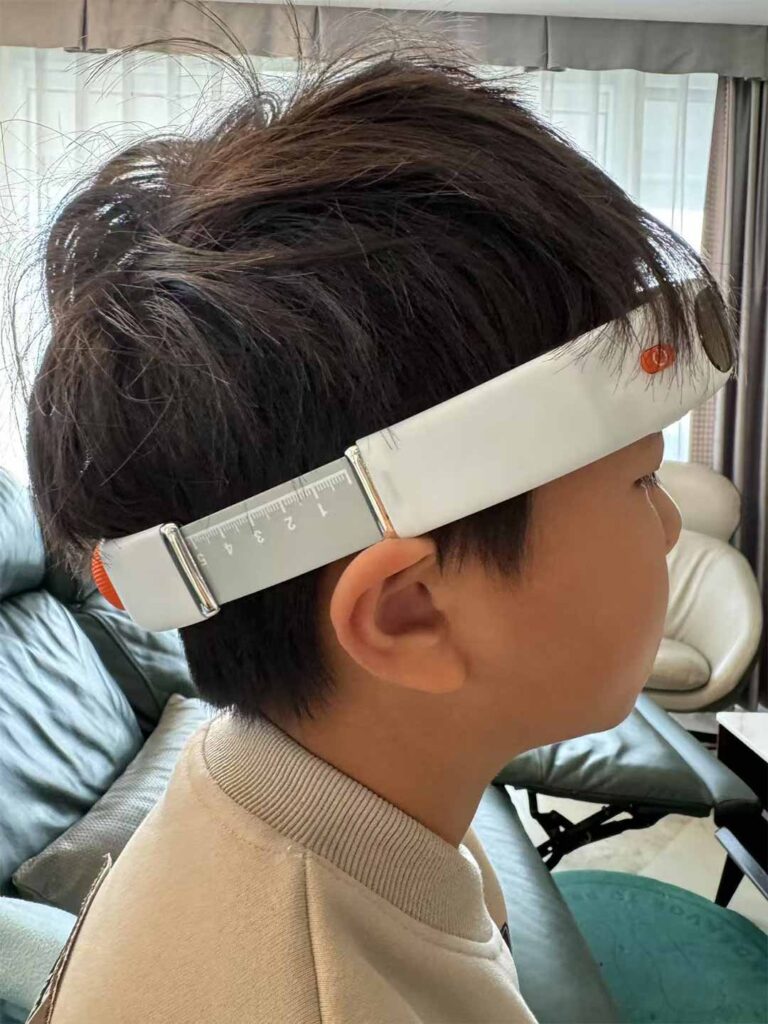
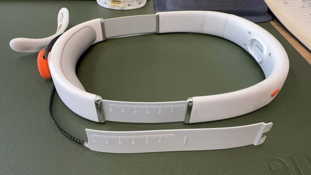
One fixed geometry could not serve the intended range of head sizes. OPD developed a segmented, flexible structure with a sliding adjustment mechanism.
The architecture provides up to 12 cm of stepless adjustment. Scale markings help users return to a known setting, while a large, textured knob gives parents and children a more secure grip. The interface was designed to reduce accidental changes after the device had been fitted.
This solution addresses more than circumference. A head-worn device also has to manage shape variation. Two users with similar circumferences may have different forehead curvature, head width, or front-to-back proportions. Flexible connections and compliant contact parts allow the system to accommodate some of that variation without relying only on higher clamping force.
What the Adjustment Prototype Needed to Prove
The mechanism could not be approved only because it moved through the required range. Testing also needed to examine:
- Whether adjustment remained smooth across the full travel
- Whether scale markings were readable and repeatable
- Whether the selected setting held during normal movement
- Whether the knob could be operated with dry or slightly damp hands
- Whether hair could become trapped near moving interfaces
- Whether the toothed band and guides tolerated repeated adjustment cycles
- Whether minimum and maximum settings created excessive gaps or pressure
- Whether assembly tolerances changed the adjustment force
The published project process records adjustment jamming as one of the issues identified during prototype evaluation. Finding that problem before production allowed the team to refine the structure while changes were still comparatively manageable.
Stage 3: Balance Stability, Contact, and Pressure Distribution
A forehead-worn EEG product has to remain stable, but stability cannot come from tightening the device indiscriminately.
Comfort depends on the total system:
- Product weight
- Center of gravity
- Contact-area size
- Contact-part compliance
- Clamping force
- Forehead curvature
- Rear support
- Local geometry around electrodes
- Duration and movement
OPD controlled the product’s total weight at approximately 150 g and shaped the wearing structure to follow the forehead. Soft contact elements and flexible joints helped distribute load, while the rear cushion increased the support area at the back of the head.
The CMF specification shows that this comfort strategy was expressed through several different parts rather than one generic foam strip. The front head support used white silicone; side sleeves used a separate silicone specification; and the rear pad combined a leather outer layer with internal foam. Each component had a different mechanical, tactile, cleaning, and production role.
A Practical Pressure-Testing Framework
The public case page confirms that fit and wearing pressure were evaluated with 1:1 prototypes and that users and doctors participated in validation. For a production wearable, these evaluations should be converted into a structured test matrix.
That matrix can include:
- Representative head-size groups across the intended population
- Minimum, middle, and maximum adjustment settings
- Correct and foreseeable incorrect positioning
- Short initial-wear checks and longer-duration sessions
- Sitting, reading, walking, bending, and normal head movement
- Feedback from the wearer and the person assisting with setup
- Inspection for redness, concentrated pressure, slipping, and contact loss
- Repeat testing after parts have aged or undergone cleaning cycles
Pressure mapping can be useful, but it should not replace observation and user feedback. A low average pressure can conceal a painful local peak. Likewise, a device that feels soft at first may gradually slip, causing the user to tighten it and create a different discomfort problem.
The design goal is not simply “minimum pressure.” It is the lowest practical pressure that still provides stable, repeatable positioning for the intended function.
Stage 4: Design an Interface Children and Parents Can Understand
The physical interface was deliberately simplified. Instead of relying on a dense display or multiple controls, the product uses core buttons and a diffused light interface.
The published status logic is:
- Blue: working or intervention mode
- Green: fully charged
- Red: low-battery warning
The light is diffused to reduce harsh visual stimulation and is linked with the app for basic device-status communication.
Color alone should never carry critical information without considering accessibility, context, and the complete risk analysis. However, for basic at-a-glance feedback, a restrained light system can lower the learning burden and help a caregiver confirm status without navigating an app for every check.
The form language also supports emotional usability. Rounded, edge-free surfaces, a white body, and controlled light-blue accents make the device feel closer to a familiar consumer wearable than an intimidating piece of clinical equipment. For products used by children, acceptance is not superficial: a technically successful device still fails the experience if the intended user resists wearing it.
Stage 5: Translate the Experience into a Part-Level CMF Specification
Color, material, and finish are often presented as an aesthetic board. For production, CMF must become a controlled part-level specification.
The project’s blue CMF document defines the following configuration:
| Component | Color | Material | Finish or Process |
| Front housing | White | ABS | Injection-molded, matte |
| Rear housing | White | ABS | Injection-molded, matte |
| Head support | White | Silicone, project-specified grade | Two-shot molding, matte |
| Side silicone sleeve | White | Silicone, project-specified grade | Matte with debossed logo |
| Rear head pad | Pantone 427 U | Leather with foam filling | Sewn construction |
| Toothed adjustment band | Pantone 427 U | Rubberized nylon | Injection-molded matte with screen-printed markings |
| Adjustment knob | Pantone 2915 U | ABS | Injection-molded matte |
| Power button | Pantone 2915 U | ABS | Injection-molded matte |
| Side decorative part | Metallic silver | ABS | Matte plating |
| Light cover | Black | PC | UV-coated surface |
| Electrode | Gold tone | Copper | Titanium-plated |
This breakdown reveals how many suppliers and processes may be involved in a seemingly simple wearable: rigid injection molding, soft-part molding, plating, UV coating, screen printing, logo embossing, sewn soft goods, foam construction, and electrode finishing.
It also shows why CMF cannot be frozen independently of engineering. Changing silicone properties can affect fit and assembly. A thicker coating can change a snap fit. A matte texture can alter cleanability. A plated decorative part may need different gate placement or quality limits. Electrode materials and finishes must be reviewed against the product’s functional, biocompatibility, durability, and regulatory requirements.
The CMF sheet represents a documented design configuration. Final production materials, suppliers, colors, and processes should always be reconciled with the released BOM, engineering drawings, validation reports, and applicable compliance file.
Stage 6: Build Prototypes for Different Questions
One prototype rarely proves that a wearable is ready for production. OPD used 1:1 mock-ups and functional prototypes to evaluate size adjustment, fit, lighting, and protection.
Different prototype types serve different purposes.
Appearance and CMF Mock-Up
This prototype evaluates proportion, visual weight, color balance, surface transitions, branding, perceived quality, and whether the product feels appropriate for its users.
Ergonomic Fit Model
This model should reproduce the critical wearing geometry, contact areas, mass distribution, and adjustment range. It may not contain complete electronics, but it must be physically representative enough to expose fit and pressure problems.
Mechanical Prototype
The mechanical build evaluates the knob, toothed band, sliding parts, flexible joints, housings, fasteners, seals, and assembly sequence. It is particularly important for identifying jamming, looseness, interference, and tolerance-stack issues.
Functional Prototype
This version integrates electronics, electrodes, light feedback, power, firmware, and the relevant sensing functions. It allows the team to assess whether ergonomic changes affect device performance and whether electronics change heat, mass, or balance.
Production-Intent Sample
Later samples should increasingly use intended materials, tooling, finishes, suppliers, and assembly methods. A 3D-printed fit model cannot fully predict molded-part shrinkage, silicone compression, plated-part appearance, seal performance, or production variation.
OPD’s product prototyping process connects physical validation with industrial and mechanical design so that prototype findings can be translated back into controlled design changes.
Stage 7: Test the Complete Wearable System
After prototypes confirmed the general direction, the project moved into testing and optimization. The published process includes material safety, IPX4, electrical-safety, fit, and comfort evaluation, with participation from users and doctors.
For a wearable device, a complete validation plan may cover several layers.
Fit and Stability
- Intended head-size coverage
- Forehead and rear-pad contact
- Slipping or rotation during movement
- Repeatability after removal and re-wearing
- Adjustment retention over time
Comfort and Skin Contact
- Local pressure and redness
- Edge pressure around soft and hard transitions
- Heat and moisture accumulation
- Hair pulling or pinching
- Contact after repeated cleaning and material aging
Interaction and Use-Related Risk
- Correct orientation and placement
- Adjustment by children and caregivers
- Recognition of light states
- Charging and power control
- Foreseeable misuse
- Cleaning and storage behavior
Mechanical Reliability
- Adjustment-cycle testing
- Joint and band fatigue
- Knob torque and retention
- Drop and impact resistance
- Fastener and enclosure integrity
- Wear of markings, coatings, and logos
Environmental and Protection Testing
- IPX4 splash-resistance verification
- Sweat and skin-oil exposure where relevant
- Temperature and humidity
- Cleaning-agent compatibility
- Packaging and transportation conditions
Electrical, Sensing, and Software Performance
- Electrode contact and signal stability
- Battery and charging behavior
- Firmware reliability
- Status-light accuracy
- App communication
- Fault states and recovery
The exact test methods and acceptance criteria must be based on intended use and target-market requirements. An IP rating, skin-contact claim, or medical-device claim should be supported by the appropriate documented testing rather than inferred from material datasheets or prototype appearance.
Stage 8: Refine the Design for Manufacturing and Assembly
Once a wearable performs correctly, it still has to be manufactured repeatedly.
This project’s segmented construction created several DFM and DFA considerations:
- Tolerance between sliding adjustment parts
- Tooth geometry, strength, wear, and molding consistency
- Knob texture, torque, and assembly method
- Bonding or retention of silicone sleeves
- Alignment between the light source and PC light cover
- Sealing around housing splits, controls, and interfaces
- Electrode positioning and retention
- Soft-pad attachment and replacement strategy
- Cosmetic transitions between matte plastic, silicone, plating, and soft goods
- Prevention of incorrect assembly
The internal layout also had to support the 150 g weight target without sacrificing structural integrity or splash protection. Industrial design and mechanical design therefore remained connected: changes to curvature, contact area, or adjustment architecture could affect PCB space, wiring, battery location, sealing, fasteners, and the product’s center of gravity.
From CMF Intent to Quality Standard
“Matte white” is not sufficient as a production instruction. Manufacturers and inspectors need defined references, such as:
- Approved color standards and tolerance
- Texture samples
- Gloss range where appropriate
- Acceptable parting lines, gate marks, sink marks, and flow marks
- Coating adhesion and wear requirements
- Logo position, depth, or print quality
- Permitted gaps and steps between materials
- Approved limit samples for cosmetic defects
The design team should retain signed golden samples and make sure that drawings, BOM revisions, CMF files, inspection standards, and supplier specifications all describe the same released configuration.
Stage 9: Prepare Tooling, Pilot Production, and Quality Control
The final stage of the published project process included production-document completion, manufacturing-process optimization, production-line commissioning, and sample inspection.
Before mass production, the team should confirm:
- Design files and BOM are frozen under revision control
- Critical dimensions and tolerances are defined
- Tooling and trial parts have been approved
- Electronics and electrode assemblies have defined test methods
- Soft components match approved compression and surface characteristics
- Assembly work instructions are complete
- Firmware flashing and functional testing are controlled
- IPX4-related seals and assembly steps are inspected
- Cosmetic limit samples are available
- Packaging protects the adjustment mechanism and finished surfaces
- Pilot-production issues have corrective actions
A pilot build validates the production system, not only the product. It reveals operator difficulties, assembly bottlenecks, supplier variation, fixture weaknesses, cosmetic defects, and test coverage gaps that may not appear in a small engineering build.
OPD’s mold development and manufacturing support services keep designers and engineers involved while tooling and production processes are being validated. That continuity is especially valuable for wearables, where a small change in material, curvature, or assembly force can alter both comfort and functional performance.
What the Project Achieved
The completed design brought several competing requirements into one coherent product:
- A 12 cm adjustment system for a broad range of users
- Scale markings for repeatable setup
- A large textured knob for easier control
- A curved support system designed to distribute pressure
- A controlled 150 g product-weight target
- Soft contact materials and rear cushioning
- Simple, diffused status lighting
- A rounded, child-friendly visual language
- IPX4 daily-splash protection
- Production-level CMF and engineering documentation
- A process extending from research and prototyping to manufacturing preparation
The project also received four international design awards, as reported on the OPD wearable brain-computer project page.
Awards demonstrate external recognition of the design, but they are not evidence of clinical effectiveness. Clinical, therapeutic, and regulatory claims require their own appropriate evidence and market-specific review.
Five Lessons for Wearable Product Developers
1. Fit Is a System, Not a Dimension
Head circumference is only one variable. Curvature, contact geometry, weight distribution, friction, movement, and adjustment behavior all influence fit.
2. Comfort and Functional Contact Must Be Tested Together
Reducing clamping force may feel better but destabilize a sensor. Increasing cushioning may change contact or cleaning behavior. Evaluate comfort with the real functional architecture as early as possible.
3. Representative Users Matter More Than the Design Team
A wearable that fits its designers is not validated. Test across the intended range of users and include the caregivers, installers, cleaners, or clinicians who interact with the product.
4. CMF Decisions Have Engineering Consequences
Silicone properties, coatings, textures, soft goods, and colors influence tolerance, durability, assembly, inspection, and compliance. Release CMF as controlled production data.
5. Production Feedback Must Return to the Design Team
Tooling trials and pilot builds will reveal issues. The people who understand the original ergonomic and interaction intent should participate in decisions so that production fixes do not quietly compromise the user experience.



![product packaging design services — structural and brand packaging by OPD Design]](https://www.opd-design.com/wp-content/uploads/2025/12/packaging.jpg "OPD DESIGN | Wearable Device Design Case Study: From Ergonomic Testing to Production")