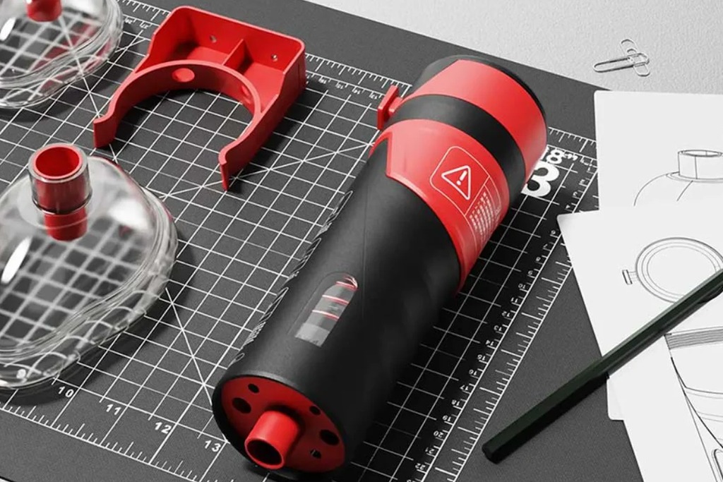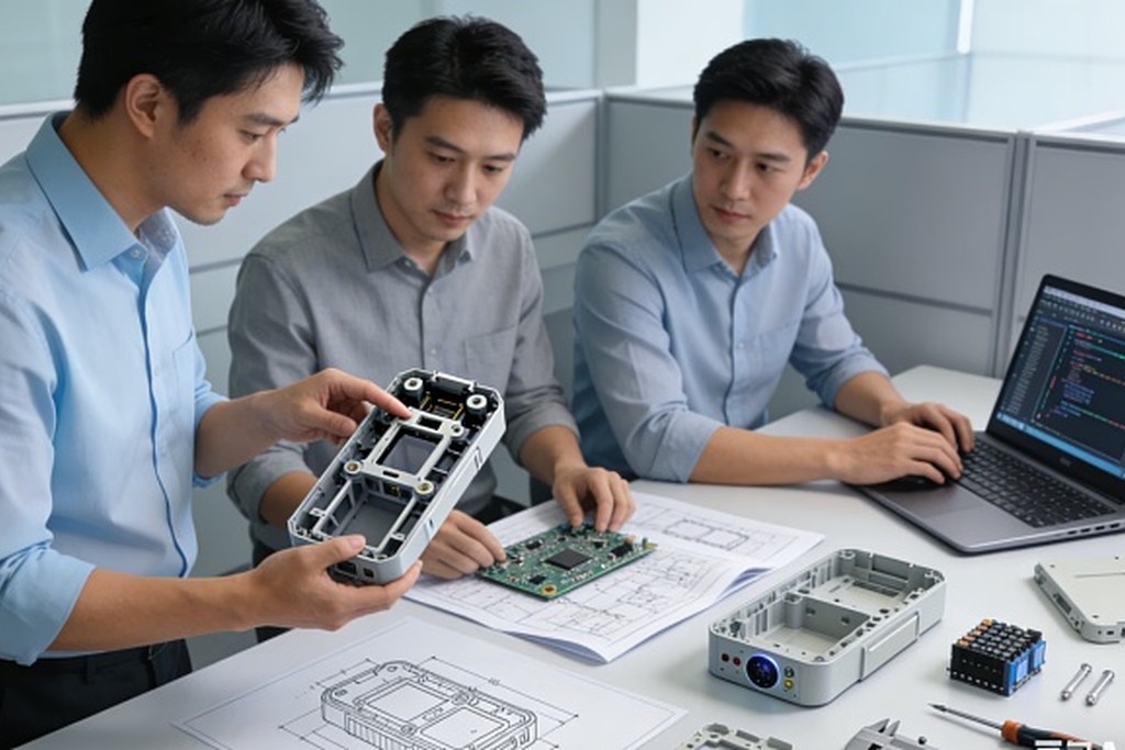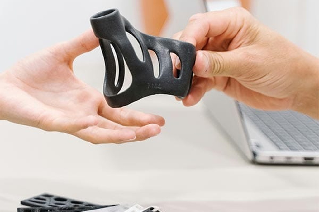

Developing a smart home appliance requires much more than adding Wi-Fi to an existing product. A successful appliance must deliver a clear everyday benefit, operate safely without constant internet access, connect reliably in real homes and remain manufacturable at the target cost.
This is a multidisciplinary challenge. Industrial design affects antenna performance and thermal management. Sensor placement affects firmware behavior. The mobile app affects setup and support costs. Material selection affects safety certification and tooling. A decision made during concept development can therefore create expensive consequences during testing or mass production.
The most effective smart home appliance development process brings product strategy, mechanical engineering, electronics, embedded software, IoT, compliance and manufacturing together from the beginning. This guide explains that process step by step—from validating the opportunity to stabilizing production.
What Is a Smart Home Appliance?
A smart home appliance combines a physical household function with sensing, electronic control and software. Connectivity may allow the appliance to exchange data with a phone, cloud service or smart home ecosystem, but connectivity alone does not make the product meaningfully smart.
A valuable smart appliance can:
- Adapt operation using sensor data
- Automate repetitive tasks
- Provide clear status and maintenance information
- Reduce energy, water or consumable use
- Diagnose faults before they become failures
- Coordinate with other devices or home automations
- Receive secure firmware improvements
- Personalize settings for different users
Examples include smart coffee machines, air fryers, ovens, robot vacuum cleaners, air purifiers, humidifiers, fans, hair-care devices, steam irons and connected home-care systems.
The central question is not “Can this product connect?” It is “What valuable outcome becomes possible because the product can sense, decide or communicate?”
Smart Home Appliance Development at a Glance
| Stage | Main purpose | Typical outputs |
|---|---|---|
| Product strategy | Define the user, problem and business case | Product brief, requirements and target cost |
| Feasibility | Prove the highest-risk functions | Proof-of-concept rigs and architecture options |
| Concept design | Align experience, form and internal system | User flows, concepts, layouts and technology plan |
| Engineering | Build the integrated product | Mechanical design, PCB, firmware, app and prototypes |
| EVT | Verify the engineering architecture | Functional and risk-control evidence |
| DVT | Verify the production-intent design | Reliability, usability and pre-compliance results |
| Certification | Demonstrate applicable conformity | Test reports, technical files and approvals |
| PVT | Validate tooling and production processes | Pilot units, work instructions and quality controls |
| Mass production | Build consistent sellable units | Controlled output, traceability and field monitoring |
The stages are not isolated handoffs. Important risks are resolved through repeated design, prototype and test cycles.
Step 1: Define the Product Opportunity
Smart appliance projects often begin with a technology idea: a sensor, an AI feature, a connected module or a competitor feature. Technology can inspire the concept, but the development program needs a specific user and commercial problem.
Start by defining:
- Target users and purchase decision-makers
- Primary environment and installation conditions
- Existing alternatives and user frustrations
- The appliance’s essential physical function
- The connected or intelligent benefit
- Target retail price and business model
- Planned sales regions
- Expected product lifetime and support period
- Forecast production volume
- Brand and channel requirements
Research should include observation, interviews, competitor teardown, review analysis and retailer or service feedback. Users frequently describe symptoms rather than root causes. For example, a request for “more automatic modes” may actually reflect uncertainty about which setting to choose.
Define the Connected Value Proposition
Connectivity should support a task that matters. Useful propositions can include:
- Remote status for a process that takes time
- Automatic replenishment of filters or consumables
- Energy optimization based on occupancy or air quality
- Guided maintenance and fault diagnosis
- Coordination with a wider smart home ecosystem
- Personal routines transferred between devices
- Software updates that improve performance or security
Avoid features that merely duplicate a nearby physical control. Asking a user to open an app to switch on an appliance within reach often adds friction rather than value.
Separate User, Product and Business Requirements
These categories are related but not identical.
| Requirement type | Example |
| User need | “I want to know when the water tank needs attention.” |
| Product requirement | The appliance shall detect and report a low-water state within a defined tolerance. |
| Business requirement | The product must meet the target landed cost and launch window. |
| Compliance requirement | The design must satisfy the applicable safety and radio requirements in each sales market. |
Convert broad claims into measurable requirements. “Quiet,” “fast,” “easy to clean” and “long battery life” need numerical targets and test conditions.
Step 2: Build the Product Requirements Document
The product requirements document, or PRD, gives every discipline the same definition of success. It should evolve as feasibility data improves, but changes must be controlled.
A smart appliance PRD typically covers:
- Primary and secondary use cases
- Functional modes and operating states
- Sensor and actuator performance
- Power source, consumption and charging
- Noise, thermal and environmental limits
- Size, weight, materials and appearance
- Local controls and feedback
- App, cloud and ecosystem functions
- Connectivity and onboarding
- Data, privacy and security requirements
- Reliability and expected life
- Cleaning, ingress and maintenance
- Target cost and production volume
- Certifications and target markets
- Packaging, shipping and storage
Define Normal Use and Foreseeable Misuse
Design requirements should address what users are expected to do and what they may reasonably do incorrectly.
Examples include:
- Operating with a missing or incorrectly installed component
- Blocking an air inlet
- Using the wrong liquid or consumable
- Spilling water onto controls
- Pulling a cable or lifting by the wrong part
- Repeatedly restarting after a fault
- Losing network connection during operation
- Selling, returning or giving away the appliance without resetting it
Risk reduction should rely first on product architecture and protective design, with warnings used as supporting information.
Create a Requirements Traceability Structure
Each important requirement should have:
- A unique identifier
- A source or rationale
- An owner
- A defined verification method
- Acceptance criteria
- Links to relevant risks and design outputs
- Status and supporting evidence
Traceability prevents important requirements from disappearing between the product brief, engineering drawings, firmware backlog and test plan.
Step 3: Prove Technical Feasibility
Feasibility work should attack the assumptions most likely to invalidate the product. Do not spend months perfecting the enclosure before proving the core function.
Depending on the appliance, feasibility prototypes may test:
- Heating speed and uniformity
- Airflow, filtration and pressure drop
- Cleaning performance and water recovery
- Motor torque, noise and lifespan
- Pump flow and dry-run behavior
- Sensor accuracy and placement
- Battery life and peak power
- Voice pickup in the product’s noise environment
- Wi-Fi range inside the intended enclosure
- Computer-vision or AI performance on realistic data
These prototypes can be rough. Their purpose is to create reliable evidence for architecture decisions.
Maintain a Technical Risk Register
For each high-risk assumption, record:
- What must be true for the product to succeed
- Why the assumption is uncertain
- The consequence if it is wrong
- The fastest experiment that can reduce uncertainty
- The decision threshold
- The owner and review date
Prioritize risks by impact and uncertainty. A difficult color finish may matter, but it should not take priority over an unproven sensing method that determines the product’s main value.
Compare Build, Buy and Integrate Options
Not every subsystem should be developed from zero. Certified modules, motor platforms, pumps, power supplies, cloud services and app frameworks can reduce time, but they bring constraints.
Evaluate:
- Technical fit and customization limits
- Unit cost at forecast volume
- Tooling and non-recurring engineering cost
- Certification status and conditions
- Firmware ownership and access
- Data ownership and service dependencies
- Supplier capacity and roadmap
- Second-source availability
- Security maintenance and end-of-life policy
A component that accelerates the first prototype can become a supply-chain or support risk later. The evaluation should cover the complete product lifecycle.
Step 4: Define the System Architecture
The system architecture allocates product functions across mechanics, electronics, firmware, app, cloud and external ecosystems.
Create a block diagram showing:
- Power input, conversion and protection
- Main processor and memory
- Sensors and analog interfaces
- Motors, heaters, pumps, fans, valves or lighting
- Local display, buttons, touch or audio
- Wireless radios and antenna
- Debug, programming and production-test interfaces
- Mobile app and cloud services
- Third-party ecosystems and APIs
For each function, define the source of truth. If a schedule is changed in the app while the appliance is offline, where is the authoritative value stored? If a cloud command arrives late, should it still execute? Ambiguity at this stage becomes inconsistent behavior later.
Partition Safety-Critical and Convenience Functions
Essential control and protective behavior should remain local. The cloud should not be required to stop an overheated heater, protect a stalled motor or respond to a water leak.
Create clear boundaries between:
- Real-time device control
- Safety monitoring and protective shutdown
- User interface and local configuration
- Ecosystem commands
- Cloud analytics and fleet management
- Optional content or subscription features
This separation improves safety, offline resilience and testability.
Design the Failure States Before the Happy Path
Define product behavior when:
- A sensor is disconnected or implausible
- An actuator fails to respond
- Power is interrupted
- The router or internet is unavailable
- The phone is not present
- The cloud service is unavailable
- An OTA update is interrupted
- Stored data becomes inconsistent
- The product is factory-reset or transferred to a new owner
Users should receive clear feedback and a safe recovery path. “Something went wrong” is not an adequate state model.
Step 5: Develop the Industrial Design and User Experience
Industrial design translates product positioning into form, materials, controls and physical interaction. It must develop around the engineering system rather than hide it.
Design Around Real Tasks
Map the complete user journey:
- Purchase and unboxing
- Placement, installation or charging
- First local operation
- App download and onboarding if required
- Everyday use
- Refill, emptying and cleaning
- Error recovery and maintenance
- Sharing with another household member
- Reset, resale or disposal
Observe representative users completing these tasks. The most important issue may be a grip, latch, fill line or status light rather than the app interface.
Coordinate Form, CMF and Engineering
Appearance concepts must account for:
- Internal components and assembly sequence
- Antenna clearance and RF-transparent materials
- Airflow and heat dissipation
- Water, dust, grease or hair ingress
- Acoustic paths and vibration isolation
- Structural loads and drop behavior
- Cleaning chemicals and UV exposure
- Mold direction, parting lines and draft
- Fastener access and service strategy
- Cosmetic aging and scratch visibility
Materials and finishes should be evaluated on real parts under representative heat, moisture, oils and cleaning—not only on flat color samples.
Make Product State Visible
Smart appliances operate through more states than traditional appliances. Users need to know whether the product is ready, connected, paused, updating, blocked, completed or in an error condition.
Coordinate LEDs, sounds, displays, physical controls and app messages into one consistent language. Critical functions need feedback that remains available when the app or network is not.
Step 6: Engineer the Mechanical System
Mechanical engineering turns the concept into a structure that controls forces, motion, fluids, airflow, heat, ingress and assembly variation.
Key activities include:
- Internal packaging and stack-up studies
- Mechanism and motion design
- Structural analysis and drop protection
- Sealing and drainage
- Thermal management
- Airflow and acoustic design
- Material and fastening selection
- Tolerance analysis
- Design for assembly and service
- Design for manufacturing
Treat Water, Heat and Dust as System Problems
An ingress rating or seal specification does not guarantee a reliable appliance. Water can follow wires through capillary action, condensation can form behind displays and dust can accumulate where airflow slows.
Map likely paths and test them on assembled units. Consider aging, cleaning, pressure changes, blocked drains and incorrectly seated removable parts.
Similarly, thermal analysis must include component self-heating, motors, power supplies, ambient conditions, consecutive operating cycles and restricted airflow. Validate both internal component temperatures and external touch surfaces.
Control Tolerances at Functional Interfaces
Tolerance stack-up can change seal compression, gear alignment, sensor location, button feel and cosmetic gaps. Identify critical interfaces early and allocate tolerances based on function, process capability and inspection cost.
Avoid solving every variation with tighter dimensions. Datum strategy, self-locating features, compliant elements and assembly fixtures may achieve better consistency at lower cost.
Step 7: Develop Electronics, Power and Sensing
The electronic architecture must support the appliance’s real loads and environment, not only its nominal feature list.
Define:
- Input power and protection
- Peak, average and standby consumption
- Power rails and sequencing
- MCU or application processor
- Memory for firmware and OTA
- Sensor interfaces and calibration
- Motor, heater, pump or lighting drivers
- Wireless module and antenna
- Display and audio interfaces
- Debug and production programming
- Safety isolation and grounding
Select Sensors as Installed Systems
Sensor datasheet accuracy is only one part of measurement quality. Placement, mechanical coupling, airflow, contamination, wiring, ADC performance and calibration can dominate the result.
For every sensor, specify:
- What physical variable it represents
- Required range, accuracy and response time
- Environmental exposure
- Installation and tolerance requirements
- Calibration method
- Expected drift and life
- Open, short and implausibility detection
- Safe product response to failure
Use multiple signals when a single sensor cannot distinguish important states reliably.
Design for EMC and RF Early
Motors, switching supplies, relays and heaters can interfere with sensors and radios. At the same time, a metalized enclosure, water tank, battery or motor can weaken the antenna.
Use early PCB reviews, grounding strategy, filtering, separation and representative enclosure prototypes. Run pre-compliance measurements before the layout and tooling become difficult to change.
Step 8: Develop Firmware, Connectivity, App and Cloud
A connected appliance is a distributed system. The device, phone, router, cloud and third-party ecosystem can each be online, offline or running a different software version.
Build the Device State Machine First
Embedded firmware should define allowed states, transitions, timeouts and fault responses. Typical responsibilities include:
- Sensor acquisition and filtering
- Actuator and process control
- Local interface behavior
- Interlocks and fault handling
- Configuration and calibration storage
- Event logs and diagnostics
- Connectivity and provisioning
- Secure boot and firmware update
- Watchdog and power-loss recovery
State transitions should be deterministic. If an operation is interrupted by power loss, the appliance must know whether to resume, cancel or ask the user to confirm.
Choose Connectivity Around the Product
Wi-Fi, Bluetooth Low Energy and Matter solve different problems:
- Wi-Fi supports household-network and cloud access with relatively high data capacity.
- Bluetooth LE is useful for nearby control, commissioning, service tools and low-power accessories.
- Matter provides a standardized smart home application layer over IP transports such as Wi-Fi, Thread and Ethernet.
A product may combine them. For example, Wi-Fi can provide cloud connectivity, BLE can assist onboarding and Matter can expose standardized controls to compatible ecosystems.
Choose the architecture based on data volume, power, range, onboarding, offline operation, ecosystem strategy and certification—not trend value.
Design Onboarding as a Product Feature
Setup failure is one of the fastest ways to turn a working appliance into a product return. The onboarding flow should explain what is happening and recover from interruption.
Test:
- Account creation and sign-in
- Bluetooth and local-network permissions
- Wrong Wi-Fi credentials
- Weak or unavailable network
- Dual-band and mesh routers
- App backgrounding or phone interruption
- Device already owned by another account
- Retry without factory reset
- Household sharing
- Router replacement
- Ownership transfer and secure reset
Measure time to first successful control and the percentage of users who complete setup without help.
Decide What Belongs in the App
The app can provide advanced configuration, history, tutorials, diagnostics and remote access. It should not become the only way to perform basic safe operation.
Use consistent names and states across the appliance and app. A command should distinguish requested, delivered, accepted, executing, completed and failed. Showing “on” because a command was sent is misleading if the appliance never received it.
Treat the Cloud as an Operated Product
Cloud development includes more than API endpoints. Plan:
- Device identity and provisioning
- User and household permissions
- Data model and retention
- Fleet monitoring and logs
- Regional deployment and latency
- Scaling and cost controls
- Backup and recovery
- Third-party service dependencies
- Customer support tools
- Service end-of-life behavior
If cloud service ends, define which device functions remain available and how users receive notice.
Step 9: Design Security, Privacy and OTA
Cybersecurity affects the entire IoT product, not only the device firmware. NIST’s consumer IoT profile identifies cybersecurity capabilities commonly needed across consumer IoT products for home or personal use. See NISTIR 8425.
The product security plan should address:
- Unique identities and credentials
- Authenticated commissioning
- Secure storage of keys and sensitive data
- Secure boot and signed firmware
- Encrypted communications
- Access control and household roles
- Protection of local and cloud APIs
- Logging without exposing secrets
- Vulnerability reporting and response
- Software component inventory
- Support period and security update policy
- Secure reset and ownership transfer
Minimize Data Collection
Define exactly which data is required to deliver the feature. Ask:
- Does this data need to leave the home?
- Does it need to identify a person or household?
- How long must it be retained?
- Who can access or export it?
- Can the same benefit be delivered with local processing or aggregated data?
Data minimization lowers privacy exposure, cloud cost and breach impact.
Engineer OTA Before the Hardware Is Frozen
OTA requires flash capacity, partitioning, a bootloader, cryptographic signing, release infrastructure and recovery behavior. Reserve resources early.
Test:
- Normal download and installation
- Power loss at different update stages
- Network interruption and retry
- Insufficient storage
- Invalid or corrupted image
- Rollback and recovery
- Staged release and fleet monitoring
- Compatibility between device, app and cloud versions
An update system that has never recovered from a forced interruption is not ready for mass production.
Step 10: Build the Right Prototypes
“Prototype” can describe several very different artifacts. Define the question each prototype must answer.
Proof of Concept
A proof of concept tests one uncertain principle, such as sensing, airflow, heating, motor torque or radio performance. It may use development boards and simple fixtures.
Appearance Prototype
An appearance prototype evaluates size, form, CMF, visual details and physical presence. It may have limited function and should not be mistaken for proof of engineering feasibility.
Ergonomic or Interaction Prototype
Foam models, weighted mockups and clickable interfaces can test reach, grip, loading, visibility and workflow before detailed engineering.
Functional Engineering Prototype
This prototype integrates representative mechanics, electronics and firmware. It is used to tune performance and reveal cross-disciplinary issues.
Production-Intent Prototype
Later units use intended materials, geometry, PCB, firmware, tooling processes and assembly methods. These are required for design verification and manufacturing validation.
Do not use a polished appearance model to claim technical readiness, and do not ask a rough engineering rig to represent final user experience.
Step 11: Run EVT, DVT and PVT
EVT, DVT and PVT provide useful gates, but their exact naming and scope vary between companies. Define entry criteria, exit criteria, sample configuration and allowed changes for each phase.
EVT: Engineering Verification Test
EVT determines whether the integrated architecture works.
Typical objectives include:
- Validate core function and performance
- Tune sensing and control
- Confirm power and thermal architecture
- Exercise primary risk controls
- Evaluate early RF and EMC behavior
- Identify mechanical weak points
- Verify firmware state transitions
EVT units may still use soft tooling or machined parts. Major architecture changes should be resolved before moving forward.
DVT: Design Verification Test
DVT determines whether the production-intent design meets the requirements.
Typical objectives include:
- Complete requirement verification
- Reliability and environmental testing
- Usability validation
- Pre-compliance and formal certification testing
- Packaging and transport testing
- App, cloud and interoperability coverage
- Material and finish validation
- Verification after design aging
DVT failures require root-cause analysis and controlled corrective action. Repeating the failed test alone may not reveal whether the change affected another requirement.
PVT: Production Validation Test
PVT determines whether the intended factory process can build the appliance consistently.
Typical objectives include:
- Validate tooling and fixtures
- Confirm assembly sequence and cycle time
- Test firmware flashing and device provisioning
- Verify calibration and end-of-line tests
- Train operators and quality staff
- Confirm traceability
- Measure yield and process capability
- Validate packaging line and finished-goods handling
PVT is not simply a small production order. It is an experiment that verifies the manufacturing system.
Step 12: Verify Safety, Performance and Reliability
A verification plan should connect product requirements, risk controls and applicable standards to objective evidence.
| Test area | Typical evaluations |
| Core performance | Capacity, accuracy, speed, efficiency and output consistency |
| Electrical safety | Insulation, leakage, grounding, abnormal operation and component temperatures |
| Thermal | Internal temperatures, touch surfaces, thermal cycling and blocked airflow |
| Mechanical | Drop, impact, vibration, stability, mechanism and fastener life |
| Ingress and cleaning | Water, dust, steam, spills, detergents and drainage |
| Sensors | Accuracy, response, drift, contamination, calibration and fault detection |
| Motors and actuators | Stall, jam, cycle life, noise and protection |
| EMC and RF | Emissions, immunity, range, coexistence and antenna performance |
| Software | State transitions, boundary conditions, interruption and recovery |
| Connectivity | Onboarding, weak networks, offline behavior and ecosystem compatibility |
| Security | Authentication, update integrity, credential handling and unauthorized access |
| Usability | Setup, control, maintenance, warnings and error recovery |
| Packaging | Drop, vibration, compression, storage and cosmetic protection |
Test the Worst Normal Condition
Nominal laboratory conditions hide weaknesses. Test realistic combinations such as:
- Maximum load at high ambient temperature
- Low supply voltage during motor startup
- Weak Wi-Fi while the product is operating at peak electrical noise
- Repeated cycles without complete cooldown
- A nearly full dust bin, filter or water tank
- Aged seals followed by cleaning or ingress exposure
- App and firmware versions at supported compatibility boundaries
The worst condition is often a combination, not one extreme variable.
Repeat Critical Tests After Aging
Materials creep, seals relax, coatings wear, bearings change, vents collect dust and sensors drift. Perform relevant life cycling before repeating safety and performance measurements.
Field reliability is not demonstrated by a new sample passing once.
Step 13: Plan Compliance and Certification
Market access depends on appliance category, power source, wireless technologies and target countries. Applicable requirements may include:
- Household appliance safety
- EMC emissions and immunity
- Radio authorization
- Wireless protocol qualification
- Energy efficiency and standby power
- Chemical and environmental restrictions
- Battery transport and safety
- Food-contact requirements where applicable
- Accessibility, labeling and language requirements
- Packaging and recycling obligations
The IEC 60335 series provides safety requirements for household and similar electrical appliances, with general requirements and product-specific parts. IEC describes protection against hazards including electrical, mechanical, thermal and fire risks. See the IEC’s household appliance safety overview.
Do not assume one standard applies to every appliance. A vacuum cleaner, cooking appliance, hair-care product and air-treatment device can have different particular requirements.
Add Wireless Certification to the Plan
Connected appliances may require several separate activities:
- Radio regulatory authorization for each market
- Bluetooth qualification for products using Bluetooth technology
- Wi-Fi certification or brand requirements where applicable
- Thread or Matter certification if those claims are made
The Bluetooth SIG states that Bluetooth products must complete its qualification process by the time they begin sale or distribution. See the Bluetooth qualification guidance.
For Matter, the Connectivity Standards Alliance explains that product development, testing at an authorized provider and certification application are distinct phases. It also notes that the underlying network transport must be certified by the relevant standards organization before Matter device certification. See the Alliance’s certification process.
Begin Pre-Compliance Before Tooling Freeze
Early reviews and measurements can identify problems with:
- Creepage, clearance and insulation
- Protective components
- Accessible temperatures
- Flammability and material ratings
- Grounding and wiring
- EMC emissions and immunity
- Antenna performance
- Abnormal operation
- Markings and instructions
Late certification failures can require PCB, enclosure, material or tooling changes. The compliance matrix should exist before detailed design begins.
Step 14: Design for Manufacturing and Supply Chain
Design for manufacturing, or DFM, turns a technically correct design into one that can be produced consistently at the required cost.
Apply DFM Before the Design Is Finished
DFM reviews should address:
- Material and process selection
- Mold direction, draft, wall thickness and ribs
- Part count and assembly sequence
- Fasteners, adhesives and joining methods
- Datum strategy and tolerance stack-up
- Cable routing and connector access
- Sealing and thermal-interface consistency
- Cosmetic surfaces and handling protection
- Test access and calibration
- Repair, rework and disassembly
The best time to reduce part count or simplify assembly is before tooling. After tooling, every structural change becomes slower and more expensive.
Choose Suppliers Around Critical Capability
Select suppliers based on more than quoted price. Evaluate:
- Experience with the component or process
- Quality system and traceability
- Capacity and lead time
- Engineering support
- Tooling ownership and maintenance
- Change-notification discipline
- Sub-tier supplier visibility
- Intellectual property controls
- Business continuity and second-source options
For critical motors, pumps, sensors, power components and wireless modules, understand both present capacity and lifecycle risk.
Use Production-Representative Materials Early
Machined plastic, printed resin and molded polymer can behave differently. Surface finish, stiffness, creep, heat resistance, antenna loss and seal performance may change when the manufacturing process changes.
Validate important requirements on production-intent parts before approving final tooling and certification samples.
Step 15: Develop Tooling and Assembly Processes
Tooling includes more than injection molds. It may include die-cast tools, stamping dies, extrusion dies, ultrasonic welding fixtures, leak-test fixtures, calibration rigs, programming stations and packaging tools.
Manage Tooling With Measurable Approval Criteria
For each tool, define:
- Ownership and storage location
- Expected life and maintenance
- Approved material and process
- Critical dimensions
- Cosmetic standards
- Sample inspection plan
- Modification responsibility
- Golden samples and limit samples
First-tool samples should be evaluated functionally, not only cosmetically. Warpage or shrinkage can change sealing, airflow, mechanism alignment and antenna position.
Design the Assembly Process
Create a station-by-station flow covering:
- Incoming material verification
- Subassembly preparation
- Firmware flashing and secure provisioning
- Mechanical and electrical assembly
- Adhesive or sealant application
- Torque-controlled fastening
- Calibration
- End-of-line functional tests
- Cosmetic inspection
- Packaging and serial-number association
Use fixtures and poka-yoke features to prevent incorrect orientation, missing parts and inconsistent pressure or torque.
Protect Device Identity in Production
Connected products need secure handling of serial numbers, keys, certificates and account associations. Define how identities are generated, injected, verified, backed up and protected from duplication or unauthorized access.
Production systems should prevent a failed unit from leaving with active credentials that are later reused incorrectly.
Step 16: Validate the Pilot Run
The pilot run exposes problems that small engineering builds cannot reveal. Use it to measure the process, not merely to create launch inventory.
Track:
- First-pass and final yield
- Defects by station and root cause
- Assembly cycle time
- Rework and scrap
- Calibration distribution
- End-of-line test failures
- Cosmetic defect patterns
- Supplier lot variation
- Firmware and identity errors
- Packaging damage
Set Production Limits From Engineering Evidence
End-of-line thresholds should detect weak products without rejecting normal variation. Correlate production measurements with verified product performance.
For example, a motor current limit should reflect supply voltage, temperature, mechanical load and component tolerance. A limit copied from one prototype is unlikely to be robust.
Close Problems Through Root-Cause Analysis
When a pilot defect appears, identify whether it comes from design, material, tooling, process, supplier variation, test method or operator instruction. Temporary screening can protect the build, but it is not a substitute for corrective action.
Freeze the product only after critical risks are understood and production processes demonstrate stable output.
Step 17: Launch and Support the Product Lifecycle
Mass production is the beginning of field learning. Establish systems to connect factory, app, cloud, customer support and engineering data.
Monitor:
- Activation and onboarding success
- Firmware and app versions
- Connectivity failures
- Product error events
- Customer contacts and return reasons
- Warranty failure rates
- Supplier and production lots
- OTA success and rollback
- Cloud cost and service availability
- Security reports and patch status
Use Field Data Carefully
Telemetry can reveal patterns, but it should be minimized, protected and interpreted in context. A high number of disconnects may indicate poor home coverage, firmware behavior, a weak antenna or a confusing reset process.
Combine data with returned-unit analysis, customer interviews and support logs before deciding on corrective action.
Control Post-Launch Changes
Changes to components, suppliers, firmware, cloud services or manufacturing processes may affect safety, compliance and user experience. Use a formal change-control process that includes impact assessment, verification and traceability.
Define End-of-Life Behavior
Before launch, decide:
- How long firmware and security updates will be supplied
- What happens when a cloud feature is retired
- Whether essential functions continue locally
- How users export or delete data
- How ownership and credentials are removed
- How service parts and recycling are handled
A product lifetime can outlast the original app platform or cloud contract. The architecture should account for that reality.
From Smart Appliance Idea to a Manufacturable Product
The path from concept to mass production is a sequence of evidence-based decisions:
- Define a valuable user and business opportunity.
- Translate it into measurable requirements.
- Prove the highest-risk technology.
- Integrate industrial design, mechanics, electronics and software.
- Verify the architecture through EVT.
- Verify the production-intent design through DVT and certification.
- Validate tooling, assembly and quality controls through PVT.
- Ramp production while monitoring yield and field performance.
The project becomes more predictable when engineering, user experience, compliance and manufacturing are considered together from the beginning.
OPD supports smart home appliance development from product strategy to mass production. Its capabilities include industrial design, mechanical and electronic engineering, sensors, motors, heating and power systems, embedded software, Wi-Fi, Bluetooth/BLE, Matter, app integration, OTA, prototyping, DFM, tooling and manufacturing support through the Shenzhen supply chain.
Explore OPD’s smart home appliance product development services to discuss how to turn your appliance concept into a reliable, connected and manufacturable product.