
TL;DR: Assembly complexity is one of the biggest hidden costs in hardware development. Specifically, products with too many parts take longer to build, require more labor, and generate more defects. Consequently, this guide walks you through the core principles of Design for Assembly (DFA) — how to reduce part count, design self-aligning features, minimize fasteners, and build products that factories can assemble quickly. Furthermore, read on to learn how DFA connects to DFM, which tools help during design, and what common mistakes to avoid before tooling up.

Why Design for Assembly Matters for Hardware Founders
Every hardware product must be assembled. However, Design for Assembly (DFA) is the practice that separates products costing a fortune to build from those that flow smoothly through production. Whether the assembly happens in a Shenzhen factory or a local contract manufacturer, every assembly step costs money. Moreover, the more complex the assembly process, the higher the per-unit cost.
Design for Assembly is the practice of designing products specifically for easy and cost-effective manufacturing. Essentially, DFA asks one core question: “Can this product be built with the fewest parts, in the least time, with the lowest risk of error?”
Notably, DFA is closely related to Design for Manufacturing (DFM). While DFM focuses on making individual parts easy to produce, DFA focuses on making those parts easy to put together. In practice, these two disciplines work hand in hand. A part that is perfectly moldable but impossible to assemble is still a bad design.
Furthermore, assembly costs are rising globally. Labor rates in China have increased significantly over the past decade. Therefore, designs that rely on many manual assembly steps are increasingly expensive. For hardware startups, where every dollar counts, DFA is not optional — it is a survival skill.
In fact, studies show that assembly can account for 40–60% of total manufacturing cost in complex products. Consequently, even modest improvements in assembly efficiency can reduce your product cost by 10–20%.
“The best part is the one that does not exist. The best assembly step is the one that does not happen.”
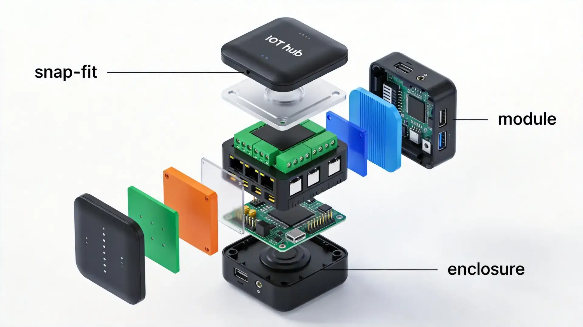
— This principle, widely cited in mechanical engineering, captures the core philosophy behind DFA. When you eliminate a part, you eliminate every assembly step, every fastener, and every quality check associated with it.
The Golden Rule of Design for Assembly: Reduce Part Count
The single most powerful DFA principle is also the simplest: use fewer parts.
Each part in your product introduces assembly work. Additionally, each part has a cost — material, tooling (if moldable), and procurement. Furthermore, each part is a potential failure point. Consequently, eliminating a part eliminates all of these costs and risks simultaneously.
In practice, how do you reduce part count? Here are proven approaches:
Combine multiple functions into one part. For example, a single molded housing can serve as the outer shell, the structural frame, and the mounting surface for internal components. Moreover, ribs and bosses can be integrated into the same part rather than added as separate pieces.
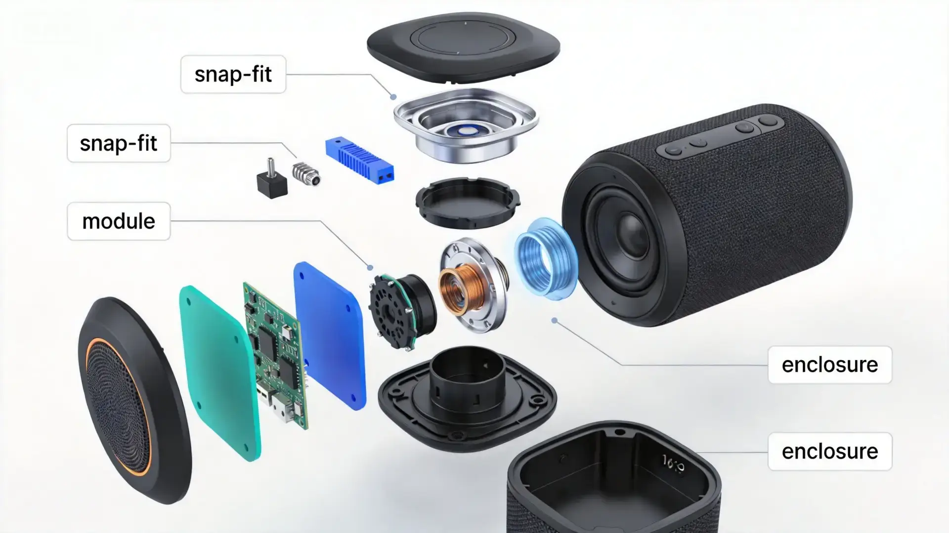
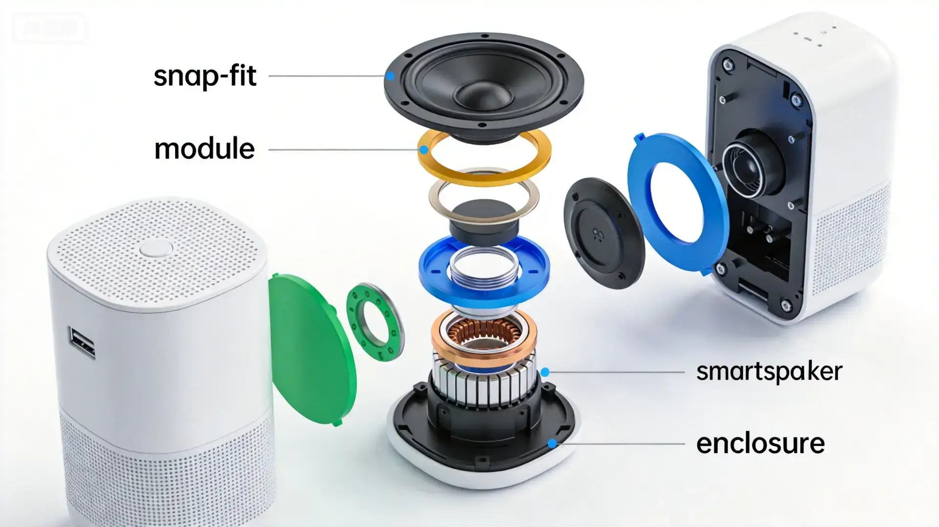
Use snap-fits instead of screws. Snap-fits are interlocking features molded directly into plastic parts. Therefore, they require no separate fasteners. Furthermore, they enable tool-free assembly and disassembly, which reduces labor cost and time.
Design multi-shot overmolded assemblies. Overmolding bonds multiple materials or components during a single molding cycle. Therefore, it replaces separate parts and their assembly steps.
Eliminate hardware that serves only to hold other hardware. If a part exists only to attach another part, consider redesigning both parts so one holds the other directly.
At OPD Design, our mechanical design team applies this principle to every product. For example, a recent consumer device project reduced the part count from 28 to 14 by redesigning the internal chassis. As a result, assembly time dropped by 45%, and the product cost fell by 18%.
Design Self-Aligning Features for Design for Assembly
After reducing part count, the next priority is making remaining parts easy to position and join. In fact, if parts cannot align themselves during assembly, operators waste time — and mistakes happen.
Self-aligning features guide parts into their correct position automatically. Essentially, they “click” parts into place before the final fastening step. This has three key benefits:
• Faster assembly: Operators do not need to hold and reposition parts manually.
• Fewer errors: If a part is in the wrong position, the alignment feature prevents final insertion.
• Lower skill requirements: Assembly can be done by workers with less training.
Here are the most common self-aligning features used in hardware product design:
Chamfers and Tapered Leads
A chamfer is a beveled edge that guides a part into its mating feature. Specifically, chamfers compensate for positional tolerance between parts. Therefore, they allow parts to self-locate even when alignment is not perfect. Typically, a lead-in chamfer of 0.3–0.5mm at 30–45° is sufficient for most plastic parts.
Locating Pins and Holes
Locating pins fit into holes or slots to position parts precisely. Importantly, pins should be slightly tapered to aid insertion. Moreover, the pin diameter should be smaller than the hole diameter to allow clearance. Additionally, use at least two pins per part to prevent rotation.
Dovetail and Tongue-and-Groove Joints
These interlocking features guide parts along a single axis during insertion. Moreover, they resist separation in directions perpendicular to the insertion axis. Therefore, they are ideal for panel assemblies and structural connections.
Snap-Fit Features
Snap-fits are resilient clips that lock two parts together. However, they must be designed carefully. Specifically, the cantilever beam must deflect enough to clear the catch feature, then snap back into position. Furthermore, the material must have sufficient flexibility. At OPD, our product prototyping process tests snap-fit designs with prototype builds before tooling.

Minimize Fasteners in Your Design for Assembly Strategy
Screws, bolts, and nuts are the most common fasteners in hardware products. However, each fastener requires a separate assembly step. Moreover, fasteners add cost, introduce failure points, and require tool maintenance.
Therefore, DFA encourages minimizing fasteners wherever possible. Here is how:
Use snap-fits for non-structural connections. For example, battery covers, access panels, and cosmetic components can often be held by snap-fits alone. As a result, assembly requires zero tools.
Design welded or bonded joints. Ultrasonic welding or adhesive bonding joins plastic parts permanently. Consequently, this eliminates fasteners between those parts entirely. However, bonded joints are not easily serviceable, so consider repairability when choosing this approach.
Integrate fastener features into moldable parts. For example, heat-staked posts, expansion clips, and retaining rings can be molded directly into plastic parts. Therefore, no separate fasteners are needed.
Reduce the number of identical fasteners. If your design requires screws, use as few as possible and make them all the same size. Consequently, this simplifies inventory, speeds up the assembly process, and reduces the chance of using the wrong screw.
According to Boeing’s DFA handbook, reducing the number of fasteners by half can cut assembly time by 20–30%. Moreover, the same principle applies to consumer electronics at any scale.
When fasteners are unavoidable, choose them wisely. For example, use self-tapping screws instead of machine screws where possible. Additionally, specify Torx or Phillips heads rather than slotted heads to reduce driver slippage. Furthermore, consider whether a loose parts kit or a tape-and-reel automated feeding system is appropriate for your production volume.
Design for Automated Assembly
If your production volume is high enough, automated assembly becomes an option. However, automation imposes strict design requirements. Consequently, designing for automation from the start is far easier than retrofitting a manual assembly design.
Here are the key DFA principles for automated assembly:
Design for pick-and-place. Parts must be orientable and stable on a feeder. Specifically, avoid flat, thin parts that stick together. Moreover, add grip surfaces or texture to parts that are slippery.
Ensure parts are symmetrically stable. Parts should sit flat without rocking. If a part is not stable, orienting it for placement becomes difficult and unreliable.
Provide clear insertion axes. Robots insert parts along a single axis. Therefore, features that require rotational or angular insertion are difficult to automate.
Avoid delicate features. Parts that can bend, break, or contaminate during handling are not automation-friendly. Specifically, thin pins, exposed springs, and unsealed adhesives all create problems on automated lines.
The ISO 9283 standard defines performance requirements for industrial robots. However, most startups begin with manual assembly and transition to automation as volumes grow. Notably, working with a product development partner that understands both manual and automated assembly helps you design for this transition.
DFM vs DFA: Understanding the Connection
Design for Manufacturing (DFM) and Design for Assembly (DFA) are often mentioned together. Nevertheless, they address different stages of production:
| Aspect | DFM (Design for Manufacturing) | DFA (Design for Assembly) |
| Focus | Producing individual parts | Combining parts into a finished product |
| Goal | Reduce part cost and defects | Reduce assembly time and errors |
| Key Questions | Can this part be made efficiently? | Can parts be joined quickly? |
| Typical Techniques | Optimize wall thickness, reduce undercuts | Minimize fasteners, add alignment features |
In practice, DFM and DFA decisions interact. For instance, adding draft angles to a molded part is a DFM requirement. However, draft angles also affect how parts stack and orient during assembly — a DFA consideration. Similarly, reducing wall thickness saves material (DFM) but may require additional ribs for stiffness, which adds part count (DFA tradeoff).
At OPD Design, we evaluate both DFM and DFA simultaneously during the industrial design and mechanical design phases. This integrated approach prevents surprises after tooling.
Assembly Sequence Planning
Designing for assembly means thinking about the order in which parts come together. Specifically, earlier decisions constrain later ones. Therefore, plan the assembly sequence during the concept phase, not after.
Here are key principles for good assembly sequence design:
Design for top-down assembly. Parts that are assembled first should not block access to parts assembled later. Therefore, consider the tool reach and line-of-sight for each step.
Make the first part the anchor. The base part — usually the product enclosure or chassis — should hold all other parts. Moreover, it should be stable and easy to fixture.
Group related functions. Components that are connected electrically or mechanically should be assembled together as a sub-assembly before final integration. For example, a display module can be pre-assembled, tested, then dropped into the main housing as a single unit.
Consider serviceability. If your product requires repair, design the assembly sequence in reverse. Therefore, parts that may need replacement during service should be accessible without disassembling the entire product.
Common DFA Mistakes Hardware Founders Should Avoid
Even well-intentioned designs fail when DFA principles are overlooked. Here are the most common mistakes:
Over-specifying surface finishes. Cosmetic requirements drive unnecessary complexity. For example, a textured exterior that requires protective film during assembly adds steps and cost. Therefore, separate functional and cosmetic requirements clearly.
Ignoring tolerance stack-up. When multiple parts are assembled, their dimensional tolerances add up. Therefore, a nominally correct design may fail to assemble due to accumulated variation. Use GD&T (Geometric Dimensioning and Tolerancing) to specify acceptable variation precisely.
Designing parts that look simple but are hard to orient. Flat rectangular parts are symmetrical — which sounds good but actually makes automated feeding difficult. Therefore, add asymmetric grip features or asymmetrical outlines to aid orientation.
Using exotic materials that complicate assembly. Some high-performance plastics are difficult to bond, weld, or coat. Therefore, consider how each material behaves during assembly, not just during use.
Failing to involve the manufacturer early. Contract manufacturers have decades of assembly experience. Therefore, share your design with them during the NPI process before tooling. Their feedback can save significant cost.
DFA Tools and Resources
Several tools help you apply DFA principles during the design phase:
CAD-based DFA analysis. Most modern CAD platforms — including SolidWorks, Creo, and Fusion 360 — offer DFA analysis tools. These tools calculate assembly time estimates, identify inaccessible features, and flag high part counts.
DFA calculators. Online tools estimate assembly cost based on part count, fastener count, and assembly complexity. These are useful during concept evaluation.
Design for Assembly handbooks. Boeing’s Design for Maintainability and Assembly guide is a widely referenced resource. Additionally, The Honda DFA Handbook provides automotive-industry insights applicable to any product.
Prototyping before tooling. Physical prototypes reveal assembly issues that CAD cannot. At OPD, our product prototyping process includes assembly path analysis and mock-up testing. Therefore, design issues are identified before expensive tooling is committed.
Frequently Asked Questions
What is Design for Assembly (DFA)?
Design for Assembly is a product design methodology focused on simplifying the manufacturing assembly process. Specifically, it aims to minimize the number of parts, reduce assembly time, eliminate specialized tools, and prevent assembly errors. Consequently, DFA reduces per-unit manufacturing cost and improves product quality.
How does DFA differ from DFM?
DFM (Design for Manufacturing) focuses on making individual parts easy to produce — for example, optimizing mold geometry or machining sequences. DFA focuses on making those parts easy to combine into a finished product. In practice, both are applied together during the design phase to achieve the lowest total manufacturing cost.
How much can DFA reduce product cost?
Studies from the Product Development and Management Association show that effective DFA implementation typically reduces assembly cost by 20–40%. Moreover, when combined with DFM, total manufacturing cost reductions of 15–25% are common. The exact savings depend on the product complexity and the starting point of the design.
Can I apply DFA to an existing design?
Yes, but changes are easier before tooling. If your design is already in production, DFA improvements may still be worth pursuing for next-generation versions. Additionally, consider whether redesign for DFA justifies a new tooling investment — the cost savings over production life often justify it.
What is a snap-fit and when should I use it?
A snap-fit is a molded feature that locks two parts together without fasteners. It works by deflecting a cantilever beam or annular ring past a catch feature, then snapping into place. Snap-fits are ideal for non-structural connections such as battery covers, cosmetic panels, and internal component brackets. However, they require careful material selection and geometry design to avoid brittle failure.
How do I know if my product needs automated assembly?
Automation becomes cost-effective at production volumes above approximately 10,000–50,000 units per year, depending on product complexity and assembly difficulty. Below this threshold, manual assembly is typically more flexible and less expensive. Therefore, design your product for easy manual assembly first. Then, design for automation transition when volumes justify it.
Conclusion
Design for Assembly is one of the most impactful decisions you make in hardware product development. Specifically, a product built with DFA principles is cheaper to assemble, easier to manufacture, and less likely to fail in the field. Moreover, DFA decisions made early — during concept and industrial design — are far less expensive to implement than changes after tooling.
The core DFA principles are straightforward. First, reduce part count wherever possible. Second, design self-aligning features to guide parts into position. Third, minimize fasteners by using snap-fits, welding, and bonding. Fourth, design for the assembly sequence, not just the finished product. Fifth, plan for automation if your volumes will support it.
If DFA feels overwhelming, partner with a team that has deep experience across product categories. At OPD Design, our mechanical design and hardware design teams apply DFA principles from the first concept sketch. Moreover, we validate assembly feasibility during product prototyping before any tooling investment is made.
Get DFA right, and your factory will thank you. Get it wrong, and you pay the price in every unit, for every year of production.