
Most products are used when people have time to look, think, and correct a mistake. An emergency device has to work in a very different context.
The user may be frightened. The person receiving help may be moving or unresponsive. The product may have remained untouched for months or years. A caregiver may have seen the instructions only once. Packaging, orientation, grip, placement, activation, feedback, cleaning, storage, and maintenance can all influence whether the device is used as intended.
This is why anti-choking device design is not simply a matter of creating suction or packaging a mechanical principle inside an attractive housing. It is a human-factors, risk-management, mechanical-engineering, and manufacturing challenge.
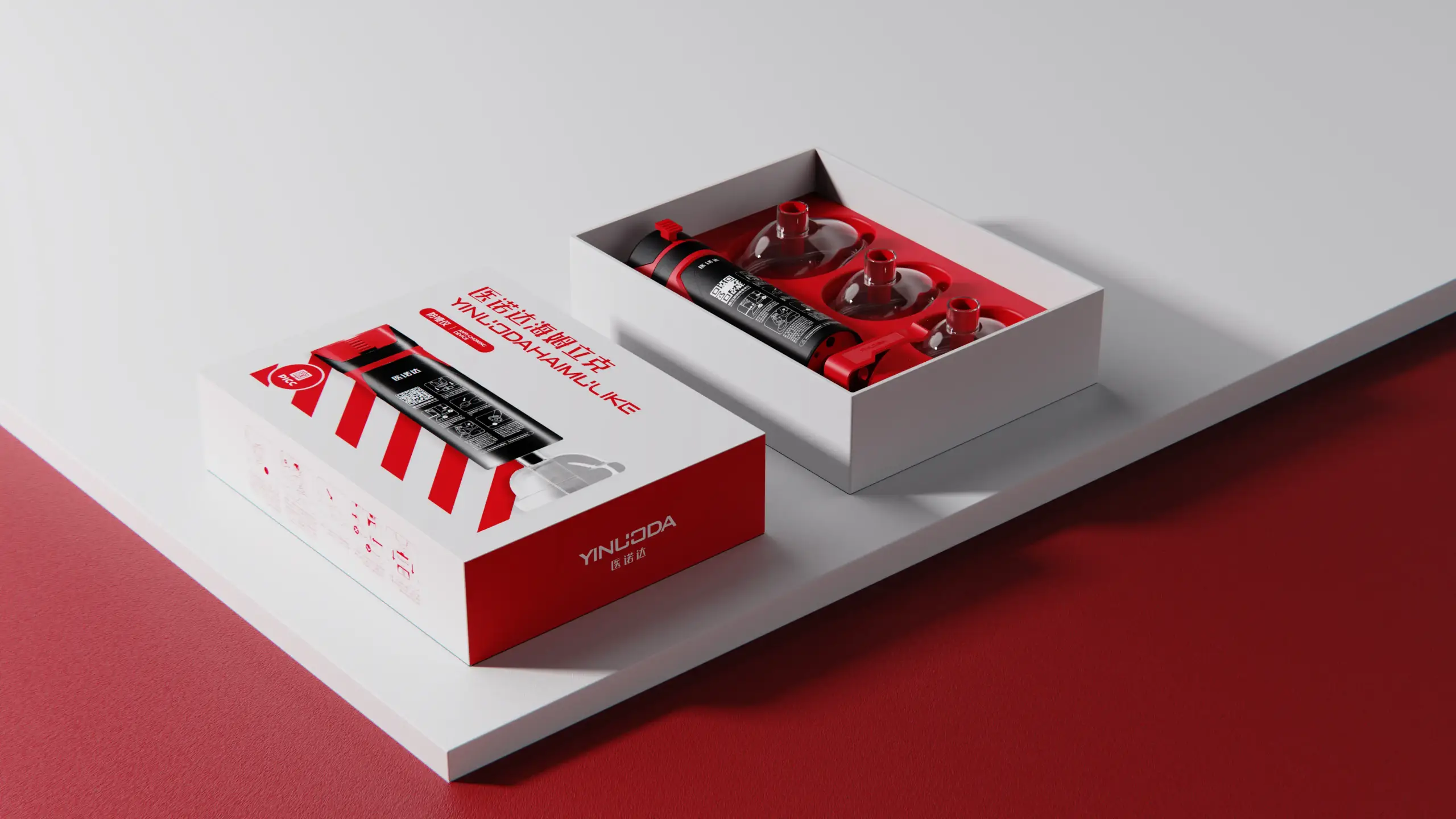
This anti-choking device design case study examines a home-use concept developed by OPD Design for a client in China. According to the published Anti-Choking Device project page, the work included field research at 28 senior-care facilities, analysis of 137 choking incidents, 27 design concepts, Pugh Matrix selection, a pure mechanical architecture, one-hand activation, a self-aligning interface, functional prototyping, packaging design, and mold development.
The most important lesson is broader than one product: for an emergency device, simplicity must be engineered and verified. Fewer visible controls do not automatically create safer use. The complete system—from storage and opening the package to positioning, activation, feedback, and post-use handling—must reduce critical errors under realistic conditions.
The Project in 30 Seconds
| Design Challenge | Published Project Response |
|---|---|
| Operation during a high-stress event | One-hand activation and a simplified mechanical interaction |
| Dependence on batteries or electronics | Pure mechanical architecture with no electronic control system |
| Positioning the contact interface | Self-aligning mouthpiece and compliant silicone interface |
| Contact comfort and user acceptance | Medical-grade silicone specified at Shore A 40 and no throat-contact design |
| Readiness around water and cleaning | Waterproof construction stated on the project page |
| Concept risk and tradeoffs | 27 concepts evaluated using a Pugh Matrix |
| Evidence from real use environments | Research at 28 senior-care facilities and analysis of 137 incidents |
| Product-development scope | Industrial design, mechanical design, functional prototyping, packaging, and mold development |
These are case-page disclosures, not independent clinical or regulatory conclusions. The public project page does not identify a final regulatory classification, marketing authorization, clinical study, production yield, or detailed verification protocol. Those items must be developed and documented according to the final intended use, claims, users, markets, and product configuration.
Why Emergency Medical Device Design Is Different
An ordinary consumer product can often tolerate hesitation. An emergency device cannot assume calm, frequent practice, ideal lighting, both hands, or a perfectly cooperative user.
The use context can include:
- Severe time pressure
- Fear and divided attention
- Limited familiarity with the product
- Different caregiver strength and hand size
- A standing, seated, lying, or moving person
- Low light, noise, crowding, or restricted access
- Contamination, moisture, food residue, or gloves
- Long storage between inspections
- Confusion between standard first-aid actions and device use
Human factors therefore has to cover more than the shape of the handle. The U.S. FDA’s human factors and medical devices overview describes a medical-device user interface as all elements people interact with while preparing, using, and maintaining the device—including packaging, labeling, and training materials. Its human-factors guidance focuses on minimizing use-related risk and confirming that intended users can use a device safely and effectively under intended conditions.
For an anti-choking device, the critical user journey may include noticing the emergency, deciding what action is appropriate, locating the product, opening the package, recognizing its orientation, positioning it, creating the intended interface with the face, activating the mechanism, interpreting the result, deciding what to do next, and handling the device afterward.
Each step can create a failure opportunity. Good industrial design makes the sequence more visible; good engineering makes the action repeatable; good usability work tests whether the intended sequence still holds under stress.
Project Background: A Mechanical Home-Use Anti-Choking Concept
The client brief called for a non-wearable device with no electronics and minimal dependence on prior training. The project page describes the result as a home-use anti-choking device based on the principles of the Heimlich maneuver, while also referring to directional airflow, pressure control, and a face-contact interface.
That combination created several connected design goals:
- Make the product immediately recognizable as an emergency tool
- Reduce setup and activation steps
- Avoid dependence on charging, batteries, software, or sensors
- Help a caregiver position the interface consistently
- Accommodate a defined range of intended users
- Reduce resistance to face contact
- Protect the mechanism during storage and cleaning
- Translate the concept into manufacturable parts and controlled assembly
- Integrate instructions and packaging into the use system
These goals can conflict. A stronger spring may increase mechanical output but also increase activation force, noise, recoil, part stress, and misuse risk. A softer interface may improve comfort but deform excessively or leak. A universal interface may reduce the number of accessories but may not fit every intended face reliably. A sealed product may be easier to clean but harder to inspect, service, or assemble.
The task was therefore not to maximize one performance number. It was to manage a network of risks while keeping the emergency-use sequence as short and understandable as possible.
Stage 1: Research the Event, Not Just the User
OPD’s published process began with field research at 28 senior-care facilities and analysis of 137 choking incidents. That research direction matters because an emergency device is shaped by the event as much as by the individual user.
Traditional user research may focus on preferences, habits, and satisfaction. Emergency-use research must also examine chronology:
- How was the incident first noticed?
- Who responded first?
- What did that person know?
- Where was emergency equipment stored?
- What delayed action?
- Which steps caused uncertainty?
- How was the person positioned?
- Were several caregivers involved?
- What happened when the first intervention did not work?
- How was the event documented afterward?
Studying incidents helps the team distinguish between a product feature and a system requirement. If users cannot locate the device quickly, improving the internal mechanism alone does not solve the delay. If a product is stored in an opaque cabinet with multiple accessories, packaging and placement become part of safety. If caregivers disagree about when the device should be used, labeling, training, and institutional protocol need attention.
Turning Observations into Design Inputs
Research findings become useful only when they are converted into controlled requirements.
A statement such as “the product must be fast” is not enough. It should be decomposed into measurable tasks and conditions, such as package-opening time, assembly steps, positioning time, activation force, number of hand changes, and time to recognize success or failure.
The project page lists targets including response below 0.5 seconds and maintenance-free operation over the product life. It also reports a 0.3-second spring response with a pressure tolerance of ±1.8 kPa. These values should be treated as published project specifications. In a formal development program, each value would need a precise definition, test setup, sample size, environmental condition, allowable drift, and traceability to a design input or risk control.
The same principle applies to qualitative goals. “No training required” is a powerful design ambition, but a safety-critical product should not rely on the phrase as a substitute for usability validation. A more testable objective is to minimize training dependence, then evaluate whether representative first-time or infrequent users can complete critical tasks using the provided labeling and instructions.
Stage 2: Define the Intended Users and Use Environment
One of the most important findings on the public project page is an inconsistency: the solution section states compatibility from ages 2 to 99, while the demand-analysis section states ages 3 to 90.
This is not a minor copywriting issue. Age range affects:
- Face dimensions and interface fit
- Airway anatomy and clinical context
- Caregiver positioning and access
- Acceptable force and pressure limits
- Mask or mouthpiece sizes
- Warnings and contraindications
- Test participants and simulated-use scenarios
- Packaging and labeling
- Regulatory strategy and supporting evidence
Before verification, the team should freeze one intended-use definition and align the product requirements, risk file, test plan, labels, instructions, accessories, and marketing claims to it. If the device is intended for materially different populations, separate interface sizes, configurations, or indications may be required.
The intended user is also not always the person receiving assistance. In a senior facility, the operator may be a trained caregiver. At home, it may be a parent, partner, relative, or bystander. Their physical capabilities, familiarity, language, vision, and emotional state can vary considerably.
The use-environment specification should address more than “home” or “care facility.” Relevant conditions can include storage temperature and humidity, shelf location, lighting, background noise, access around a bed or chair, use with gloves, cleaning agents, and the presence of other emergency equipment.
Stage 3: Simplify the Interaction Through a Pure Mechanical Architecture
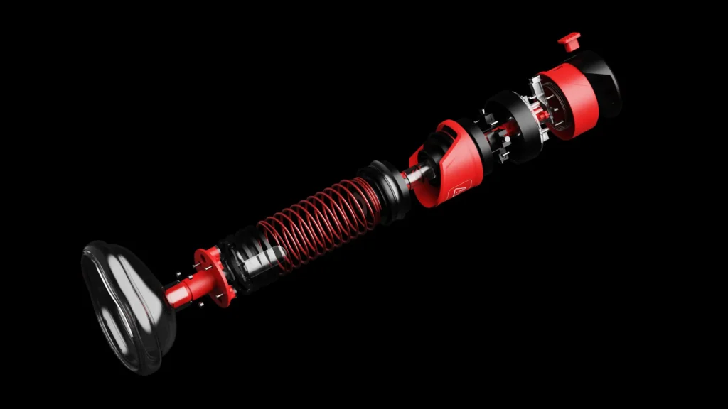
The concept uses a pure mechanical architecture. The published solution refers to a precision spring system, zero electronics, waterproof construction, and no circuit-failure risk.
Eliminating electronics can provide meaningful product-level advantages:
- No charging routine
- No battery depletion while stored
- No firmware or connectivity dependency
- No electronic start-up sequence
- Potentially simpler readiness inspection
- Reduced exposure to some liquid-related failure modes
But mechanical simplicity is not the absence of engineering complexity. The performance of a spring-driven system depends on part geometry, spring properties, friction, seal behavior, temperature, material aging, assembly tolerance, contamination, repeated cycling, and storage duration.
The mechanism therefore needs clear engineering questions:
- What output must be produced, for how long, and within what range?
- How much activation force can intended operators apply?
- Can the mechanism be activated accidentally?
- Does performance change after long-term spring compression or storage?
- What happens after drops, vibration, moisture exposure, or cleaning?
- Can wear, debris, or molding variation change friction?
- How is readiness inspected without disassembly?
- Is the device single-use, multi-use, or reusable after cleaning?
- What failure state is visible to the user?
Mechanical systems also need tolerance architecture. A nominal prototype assembled by an engineer may perform correctly, while production parts at the limits of their tolerances may create higher friction, lower output, leakage, or incomplete reset. Verification should therefore examine representative and worst-case combinations, not only one carefully tuned unit.
Stage 4: Design One-Hand Operation as a Complete Task
The published case highlights one-hand activation. This can be valuable when the caregiver’s other hand is stabilizing the person, supporting the head, moving an obstruction into view, or maintaining the interface position.
However, “one-hand operation” should not mean only that the final trigger can be pressed with one hand. The complete task should be examined:
- Can the package be opened with one hand?
- Can the device be removed without changing grip?
- Is the correct orientation obvious by sight and touch?
- Can the interface be placed while supporting the person?
- Does the hand naturally land on the activation control?
- Is the required force suitable for different users?
- Can activation occur while the wrist is bent or the user is wearing gloves?
- Is accidental activation prevented without adding a confusing safety step?
- Can the user understand whether the action completed?
Grip design must consider hand-size range, wet or contaminated surfaces, and the direction of reaction force. The control should have adequate differentiation from non-controls, and the housing should provide stable hand purchase without creating sharp pressure points.
Formative usability tests can compare several control sizes, forces, textures, and orientations before detailed tooling geometry is frozen. High-fidelity simulated-use testing can later evaluate the complete sequence with representative users, packaging, labeling, and realistic environmental constraints.
Stage 5: Use Self-Alignment to Reduce Positioning Error
The project page identifies a self-aligning mouthpiece as a key concept innovation. In an emergency, self-alignment can reduce the precision demanded from the operator.
The design opportunity is to create geometry that naturally communicates:
- Which side faces the person
- Where the interface should contact the face
- Which direction the device should point
- How much pressure is required to establish contact
- Whether the device is visibly off-center
Rounded, compliant geometry can accommodate some variation and reduce local discomfort. But an interface described as universal still needs evidence across the intended population. Face size, facial hair, dentures, facial anatomy, head position, skin condition, and operator technique can all affect contact and leakage.
Self-alignment should therefore be verified, not assumed. Useful prototype studies may include:
- Dimensional fit across representative head and face forms
- Contact-area mapping
- Leak testing at different placements and angles
- Performance with realistic operator forces
- Fit with facial hair, glasses, and different head positions where relevant
- Observation of placement errors by first-time users
- Testing of intentional and foreseeable misuse
If one interface cannot deliver consistent performance across the entire intended population, a multi-size strategy may be safer and easier to validate than forcing a single geometry to cover incompatible extremes.
Stage 6: Balance Seal Performance, Comfort, and Material Control
The contact interface is specified as medical-grade silicone with Shore A 40 hardness. This places the component in a moderately soft range suitable for a compliant face-contact feature, although hardness alone does not establish safety, fit, sealing performance, or regulatory suitability.
The complete material specification may need to define:
- Exact silicone family and grade
- Supplier and approved alternatives
- Hardness tolerance
- Colorant and additives
- Cure system and post-curing requirements
- Surface finish and mold texture
- Dimensional tolerances
- Tear strength and compression behavior
- Cleaning-agent resistance
- Aging and storage behavior
- Biological evaluation requirements for the intended contact
“Medical grade” is not a complete engineering specification. The final evidence depends on the exact material formulation, manufacturing process, contact type and duration, intended users, and target-market requirements.
The interface also has to balance competing needs. Softer material can improve initial conformity but may collapse, fold, stick, collect debris, or vary more during assembly. A stiffer interface may locate more predictably but require higher force and create pressure discomfort. Geometry, wall thickness, lip design, support structure, and hardness should be developed together.
Stage 7: Reduce Psychological Resistance Without Making Clinical Claims
The case page describes a non-invasive, zero throat-contact design and reports a 63% reduction in psychological resistance during user trials.
This is a relevant design goal. A device that looks painful, invasive, complicated, or industrial may cause hesitation during an already stressful event. Form, color, material, scale, and visible mechanism can influence willingness to approach and use the product.
However, the reported 63% result should be published only with context if it is used as a marketing claim. Readers need to know what “psychological resistance” meant, how it was measured, what the comparison condition was, how many participants were involved, and whether the study population represented intended users. Without that context, the number is difficult to interpret.
The safer case-study lesson is that perceived invasiveness is a design variable worth researching. A no-throat-contact concept may reduce one source of hesitation, while a friendly, controlled visual language can make the product less intimidating. These design benefits should remain separate from claims about clinical effectiveness.
Stage 8: Explore Alternatives Before Committing to One Mechanism
OPD generated 27 concepts and used a Pugh Matrix to support selection. That is valuable because emergency-device concepts often involve tradeoffs that cannot be resolved by appearance alone.
A Pugh Matrix can compare concepts against criteria such as:
- Critical task count
- Activation time
- Required hand force
- Positioning tolerance
- Mechanical output consistency
- Seal reliability
- Misuse resistance
- Component count
- Cleanability
- Storage readiness
- Manufacturability
- Estimated cost
- Packaging volume
- Maintenance requirements
- Regulatory and evidence burden
The matrix should guide discussion rather than hide uncertainty behind scores. Safety-critical criteria may need minimum thresholds or weighting, and a concept that fails an essential requirement should not win merely because it performs well on cosmetic or cost criteria.
The published concept set included a torsion-spring mechanism, dual-stage pressure detection, and a self-aligning interface. These ideas address mechanism, feedback, and positioning as one system. The next step is to isolate and test the highest-risk principles before investing in a fully finished prototype.
Stage 9: Build Prototypes That Answer Different Questions
One prototype cannot validate the entire product. Each build should have a defined purpose, representative features, known limitations, and pass/fail criteria.
| Prototype Type | Main Question | Typical Evidence |
| Task-flow mock-up | Is the use sequence visible and understandable? | Observed errors, hesitations, hand changes, and completion time |
| Ergonomic model | Can different operators grip, position, and activate the device? | Fit, reach, force, posture, alignment, and subjective feedback |
| Interface coupon | Does the silicone geometry conform and seal as intended? | Contact area, leakage, deformation, and material comparison |
| Mechanism rig | Can the spring system deliver controlled, repeatable output? | Force/pressure curve, response time, cycle life, and variation |
| Integrated functional prototype | Do mechanism, interface, housing, and task flow work together? | System performance, misuse observations, drops, cleaning, and environmental tests |
| Production-intent sample | Do final materials, tooling, tolerances, assembly, packaging, and labeling meet requirements? | Verification results, process capability, usability validation, and pilot-build data |
Early prototypes may be intentionally inexpensive. A foam model can answer a grip question; a machined fixture can test a spring; molded silicone samples can compare interface geometry. Cost increases only when the next decision requires higher fidelity.
The dangerous shortcut is to approve tooling from an appearance prototype that does not represent final material behavior, tolerance, spring performance, sealing, assembly, or labeling.
Stage 10: Verify the Safety-Critical System
A formal test program depends on the product’s final intended use and regulatory strategy. For a mechanically powered emergency device, the verification plan may need to address the following categories.
Mechanical Output and Repeatability
Test the complete output profile, response time, peak values, duration, reset behavior, and variability across devices. Include production tolerances and appropriate environmental conditions.
Interface and Leakage
Measure performance across intended interface sizes, face geometries, placement angles, applied forces, and foreseeable leakage conditions. Confirm that compliant parts do not fold, detach, or deform unpredictably.
Activation Force and Control
Verify that intended users can activate the product while accidental activation is adequately controlled. Consider hand-size range, grip strength, gloves, wet hands, and constrained posture.
Durability and Storage
Evaluate drops, vibration, shock, spring fatigue, material aging, long-term storage, temperature and humidity exposure, packaging protection, and shelf-life assumptions. A product that is rarely used must still remain ready.
Cleaning and Liquid Exposure
If the product is reusable or exposed to cleaning, define validated cleaning steps and compatible agents. A “waterproof” claim requires an explicit method, condition, acceptance criterion, and connection to the final assembled configuration.
Biological and Material Safety
Evaluate patient-contact materials according to the final nature and duration of contact, manufacturing process, residues, cleaning, packaging, and applicable market requirements.
Packaging and Instructions
Confirm that packaging protects the device without adding unacceptable delay or confusion. Instructions, warnings, diagrams, labels, and training should be tested as parts of the interface, not added after mechanical validation.
Formative and Validation Usability Studies
Formative studies identify and reduce use problems during development. Later human-factors validation should test representative intended users performing critical tasks in realistic simulated-use conditions with the final or production-equivalent interface, packaging, labels, and training.
Manufacturing Variation
Test samples across cavities, lots, suppliers, and normal process ranges. One engineering prototype proves only that one controlled build can work; it does not establish repeatable production performance.
Stage 11: Translate the Concept into Manufacturable Parts
Once the concept and critical functions are supported by prototype evidence, design for manufacturing can begin to narrow the production solution.
The hard and soft components may require different processes and controls. Injection-molded housing parts need appropriate wall thickness, draft, ribs, bosses, parting lines, gates, ejection, and cosmetic boundaries. The silicone interface needs stable wall sections, venting, flash control, hardness control, and dimensional inspection. The mechanical system needs controlled springs, pivots, seals, sliding interfaces, and assembly forces.
Key DFM questions include:
- Can the housing be assembled without loading or distorting the mechanism?
- Are sealing surfaces protected from parting lines, flash, and ejector marks?
- Can the silicone component be installed in only one orientation?
- Which dimensions directly affect mechanical output or leakage?
- How will spring properties be specified and incoming-inspected?
- Can critical parts be measured without destructive disassembly?
- Is the device easy to assemble without hidden manual adjustment?
- How will incomplete assembly be detected?
- Can the finished product be function-tested at the end of the line?
- Are packaging and labels controlled to the same revision as the device?
Risk controls must survive the move from prototype to tooling. A hand-finished prototype may compensate for a small gap or interference. Production parts cannot depend on selective sanding, careful pairing, or an expert technician’s intuition.
Stage 12: Plan Quality Control Around Critical Functions
Emergency-device quality control should be driven by risk, not only by cosmetic inspection.
Critical-to-quality characteristics may include:
- Spring specification and installed preload
- Activation force and travel
- Mechanical output range
- Interface dimensions and hardness
- Seal integrity or leakage limit
- Reset or lock status
- Housing closure and fastener torque
- Material identity
- Label and instruction revision
- Packaging seal and accessory completeness
- Shelf-life and lot traceability information
Not every characteristic needs the same inspection method or frequency. The control plan should connect design inputs, risk controls, verification evidence, supplier controls, process validation, in-process checks, end-of-line tests, and acceptance criteria.
Pilot production is the point where the team learns whether the documented process can repeatedly build the intended product. It should record assembly time, errors, rework, functional-test results, dimensional variation, cosmetic defects, packaging problems, and operator feedback. The goal is not merely to produce a small batch; it is to expose the difference between a successful prototype and a capable production system.
Anti-Choking Device Development Checklist
Intended Use and Regulatory Strategy
- Is the device’s operating principle defined consistently?
- Are indication, user population, use environment, and use sequence frozen?
- Are first-line and second-line treatment claims clear where relevant?
- Has the target-market regulatory pathway been confirmed?
- Are marketing claims connected to specific evidence?
Human Factors
- Have intended operators and recipients been defined separately?
- Has the complete rescue sequence been analyzed?
- Are critical tasks and foreseeable use errors documented?
- Can users locate, open, orient, position, activate, and interpret the product?
- Have packaging, labeling, instructions, and training been tested with the device?
Mechanical and Interface Design
- Is mechanical output specified as a complete time-based profile?
- Are activation force, travel, feedback, and accidental activation controlled?
- Does the interface fit the full intended population?
- Are silicone grade, hardness, geometry, aging, and contact requirements controlled?
- Have tolerance stacks, leakage, friction, wear, and spring variation been evaluated?
Verification and Validation
- Does every design input have a verification method and acceptance criterion?
- Are sample sizes and worst-case configurations justified?
- Have drops, storage, aging, environment, cleaning, and packaging been tested?
- Has formative usability work shaped the design before freeze?
- Has final human-factors validation addressed all critical tasks?
Manufacturing
- Has DFM covered plastic, silicone, springs, seals, assembly, and inspection?
- Are critical-to-quality characteristics reflected in supplier and process controls?
- Can every finished device receive an appropriate functional test?
- Do released CAD, drawings, BOM, labels, and instructions share one controlled revision?
- Has pilot production demonstrated repeatable assembly and acceptable quality?
How OPD Connects Emergency-Device Design with Production
The published project scope combines industrial design, mechanical design, functional prototyping, packaging design, and mold development. That integrated scope is especially valuable for a safety-critical mechanical product because the user interface and internal mechanism cannot be developed independently.
Research findings influence the task flow. Task flow influences grip, control placement, and packaging. Interface geometry influences sealing and material selection. Material behavior influences tooling and tolerance. The mechanism influences housing strength and assembly. Manufacturing variation influences the performance the user ultimately receives.
OPD Design’s role is to keep those decisions connected from early research through engineering and manufacturing preparation. Depending on the project’s requirements, the work can include:
- Product strategy and design inputs
- Industrial design and user-interface development
- Mechanical architecture and component engineering
- Functional and ergonomic prototyping
- Human-factors support and simulated-use preparation
- Material and CMF specification
- DFM and mold development
- Packaging and instruction-system design
- Supplier coordination, pilot production, and quality planning
For medical and emergency products, regulatory and clinical specialists should be involved early. Product design is strongest when evidence, risk, compliance, and manufacturing are planned together rather than reviewed after the form is finished.
From an Emergency Concept to a Controlled Product System
An anti-choking product cannot be judged only by how quickly its mechanism moves or how simple it looks in a rendering.
The real design challenge is to create a controlled relationship between the emergency sequence, the operator, the person receiving assistance, the mechanical output, the face-contact interface, the packaging, the instructions, and the production process.
This case study shows a strong early-development direction: research real care environments, analyze incidents, define measurable requirements, explore multiple concepts, select systematically, reduce steps, guide positioning, avoid unnecessary electronic dependencies, and connect the product with prototyping, packaging, tooling, and manufacturing.
The next level of maturity comes from evidence. Intended users and age ranges must be consistent. Performance values need test definitions. Broad claims need substantiation. Human-factors validation must address critical tasks. Production controls must preserve the same configuration that was verified.
If you are developing an emergency product, home-use medical device, mechanical healthcare product, or other safety-critical hardware, OPD Design can help connect research, industrial design, engineering, prototyping, DFM, packaging, and manufacturing preparation.
Contact OPD Design to discuss your intended users, target markets, technical principle, evidence requirements, and current development stage.