
Injection Mold Development: The Complete Guide to Design, Manufacturing & Optimization
Injection mold development sits at the heart of plastic product manufacturing, shaping everything from medical devices to automotive components. This in-depth guide demystifies the mold development lifecycle, delivering proven strategies to enhance mold performance, reduce costs, and accelerate time-to-market.
1. Injection Mold Development Planning Phase

1.1 Critical Inputs for Successful Development
- Material Science Integration: Select resins (ABS, PC, PP) based on mechanical, thermal, and aesthetic requirements.
- Design for Manufacturability (DFM):
- Optimize wall thickness (1–3 mm) to prevent sink marks
- Apply 1–3° draft angles for easy part ejection
- Strategically position ribs and bosses
- Quality Benchmarks: Define SPI-class surface finishes and ISO 20457-compliant tolerances.
1.2 Feasibility Analysis in Mold Development
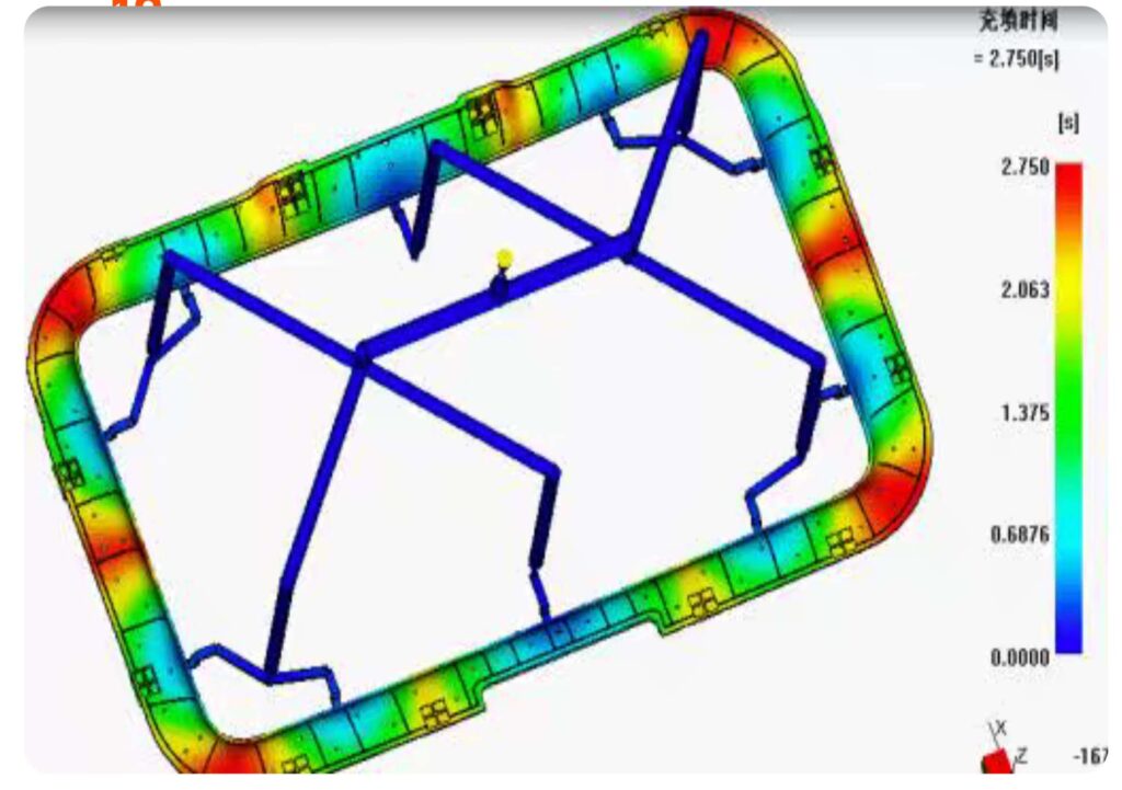
- Run mold flow simulations to predict filling patterns and cooling stresses.
- Create failure mode charts for high-risk features like thin walls or complex geometries.
- Calculate ROI: Compare standard molds (100k cycles) vs. hardened steel molds (1M+ cycles).
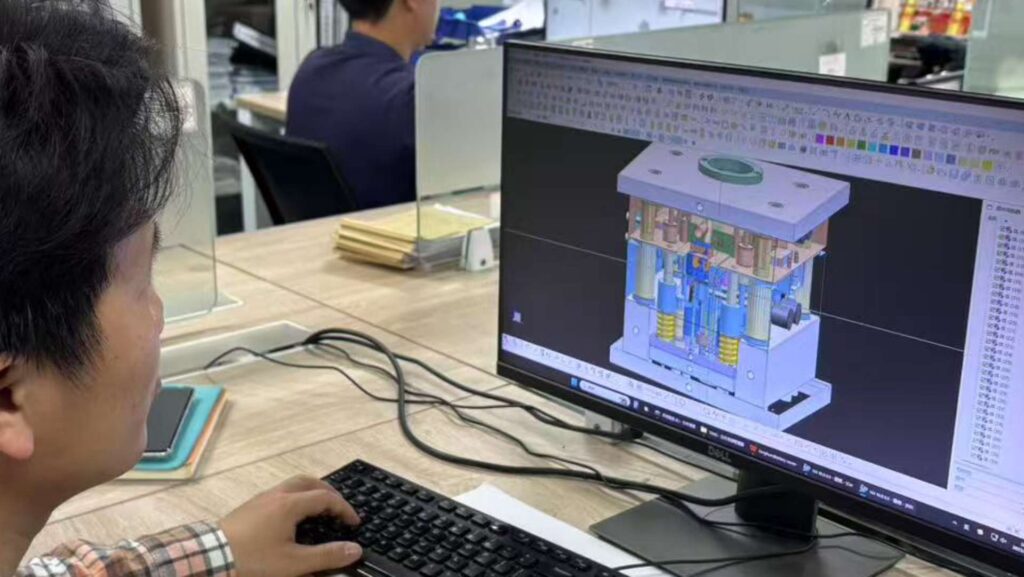
2. Injection Mold Design Engineering
2.1 Parting Line Strategies
- Use planar parting surfaces for 90% of applications; employ laser scanning for complex profiles.
- Hide parting lines under functional features or texture zones.
2.2 Advanced Gating Systems
- Cold Runners: Ideal for small batches (<10k units) with easy color changes.
- Hot Runners: Slash cycle times by 15% for high-volume production.
- Valve Gate Technology: Eliminate gate vestige on cosmetic surfaces.
2.3 Conformal Cooling Revolution
- Achieve 40% faster cooling with 3D-printed spiral channels.
- Monitor thermal stability via embedded IoT sensors (±1°C accuracy).
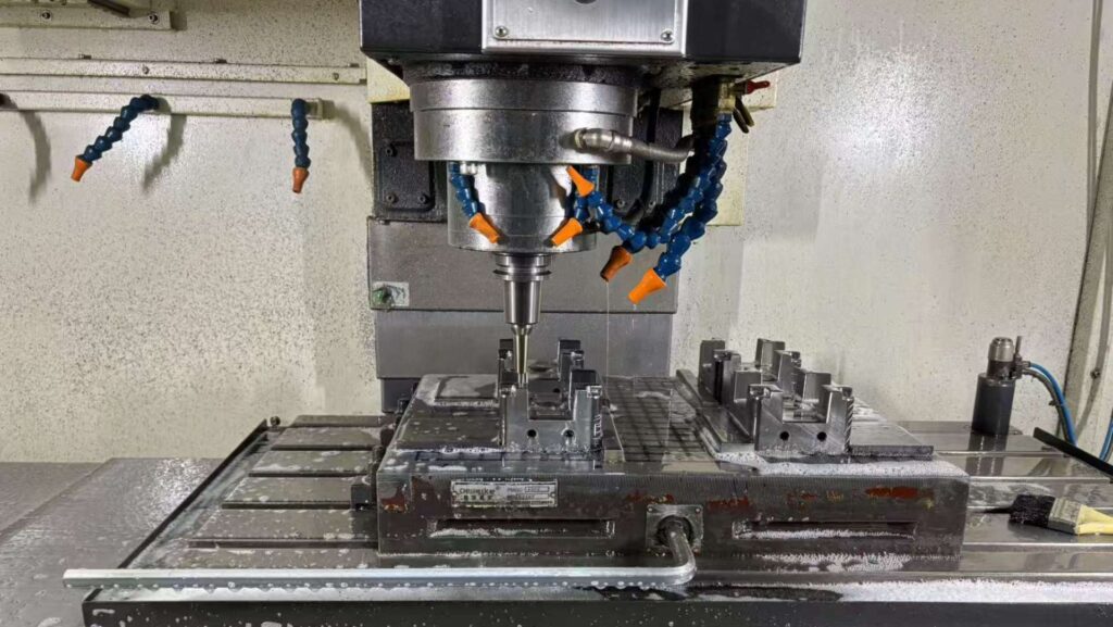
3. Precision Manufacturing in Injection Mold Development
| Process Stage | Technology | Accuracy | Equipment |
|---|---|---|---|
| Core/Cavity Machining | High-speed 5-axis CNC | ±5 μm | Mikron HSM 600 |
| Micro-texturing | Laser ablation | Ra 0.1–10 μm | GF Machining Solutions |
| Surface Hardening | Plasma nitriding | 800–1200 HV | IONBOND P40 |
| Quality Assurance | White light interferometry | 0.1 μm resolution | Alicona InfiniteFocus |
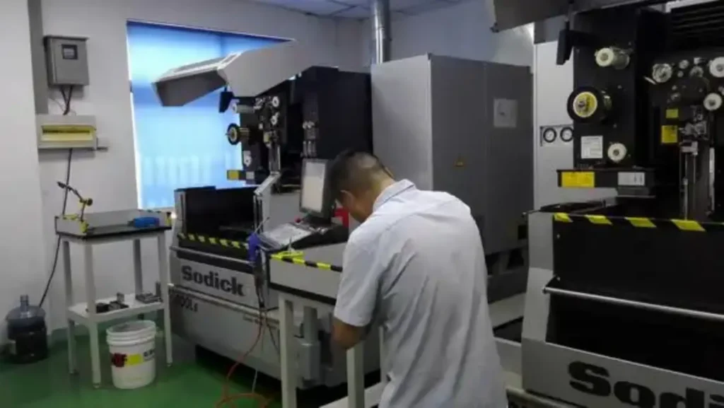
Industry Insights:
- Combine subtractive and additive manufacturing for complex inserts.
- Implement toolpath optimization algorithms to reduce machining time by 25%.
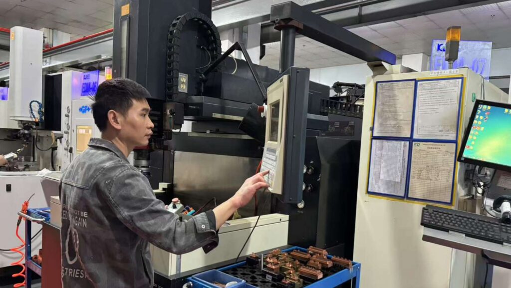
4. Injection Mold Development Validation
4.1 Scientific Mold Testing Protocol
- Dry Cycle Testing: Verify mechanical functions without material.
- Short Shot Analysis: Optimize gate locations and venting.
- DOE (Design of Experiments): Identify optimal packing pressure/temperature matrix.
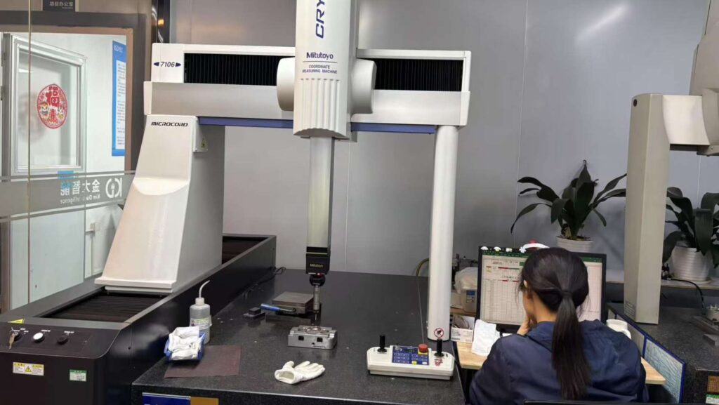
4.2 Defect Elimination Matrix
| Issue | Technical Cause | Mold Development Solution |
|---|---|---|
| Burn marks | Trapped air in cavities | Add vacuum vents (0.02–0.05 mm depth) |
| Splay | Moisture in material | Install mold dehumidification system |
| Dimensional drift | Uneven cooling | Rebalance conformal cooling channels |
5. Sustaining Injection Mold Development Excellence
5.1 Predictive Maintenance Framework
- Real-time Monitoring: Track wear on sliding cores with acoustic emission sensors.
- AI-Powered Analytics: Predict failure points 500 cycles in advance.
- Automated Lubrication: Grease guide pillars every 1k cycles via robotic systems.
5.2 Circular Economy Practices
- Remanufacture worn molds using laser cladding technology.
- Recycle H13 steel from retired molds for new inserts.
6. The Future of Injection Mold Development
- Generative Design: AI algorithms create organic mold structures with 50% less material.
- Digital Twins: Virtual clones reduce trial costs by 70%.
- Nanocoated Molds: Graphene coatings enable 10x longer service life.
The Eight Core Systems Inside an Injection Mold
Every injection mold is built from eight subsystems that work together. Understanding them helps you read a tooling quote and spot the design decisions that will drive cost.
1. Gating System
The path molten plastic takes from the nozzle into the cavity, including sprue, runners, and gates. Gate location and type determine fill quality, weld line position, and how much material is wasted in the runner. Hot runners cost more upfront but eliminate runner scrap in high-volume production.
2. Guiding System
Guide pillars and bushings align the two mold halves as they close. Poor alignment shows up as uneven wall thickness, flash, or accelerated wear on the mold. This is a low-cost system that causes expensive problems when neglected.
3. Forming System
The cavity, core, and inserts that give the part its final geometry. This is where part design meets tooling design, because draft angles, wall thickness, radii, and shut-off surfaces all live here. Every detail in this system is machined to tolerances measured in microns.
4. Mold Temperature Control and Cooling System
Cooling channels determine how fast the part solidifies and, therefore, your cycle time. Cooling typically accounts for 60 to 70 percent of the molding cycle. Conformal cooling, which follows the part contour and is often 3D printed, can cut cooling time by up to 40 percent on complex geometries.
5. Ejection System
Ejector pins, sleeves, and plates push the finished part out of the mold. Ejection marks are often the first cosmetic defect a founder notices. Pin placement must avoid thin walls, cosmetic surfaces, and areas that will be visible on the assembled product.
6. Venting System
Air and gas trapped in the cavity must escape as plastic fills it. Inadequate venting causes burn marks, short shots, and weld lines. Vents are shallow, typically 0.02 to 0.03 mm, and easy to overlook in a tooling review, but they are a common source of first article failures.
7. Core-Pulling System
Slides, lifters, and hydraulic cylinders form undercuts, side holes, and internal features that cannot be released along the main parting line. Every core pull adds tooling cost and maintenance. If a design has three or more pulls, ask whether a redesign could eliminate one.
8. Fixing and Supporting Structure
Base plates, support pillars, and connecting screws hold everything in alignment under injection pressure. This system is invisible in the finished part but determines whether the mold holds tolerance over a million cycles.
None of these systems works in isolation. A gate change affects cooling, cooling affects warpage, warpage affects ejection. That is why DFM review and mold design have to happen together, not sequentially.
Why Injection Mold Development Matters
With 68% of plastic part defects traceable to mold design flaws, mastering injection mold development is non-negotiable. Leading manufacturers now achieve:
- 30% faster development cycles via hybrid prototyping
- 22% cost savings through AI-optimized cooling designs
- 99.98% first-pass yield with digital twin validation